

Bosch · Piezoelectric (AC)
Bosch KS4-P knock sensor
The Bosch KS4-P is a broadband piezo knock sensor for 3-25 kHz with 26 ± 8 mV/g sensitivity at 5 kHz. Pin 1 is Sig+ and pin 2 Sig−. It bolts to the block with an M8 screw at 20 ± 5 N·m and must sit flat on its brass sleeve. Order 0 261 231 173 (RB-Kp.1 connector) or 0 261 231 188 (Jetronic).1
Key specifications
Measures: Structure-borne engine vibration in the knock band. Output: Piezoelectric (AC).
Pinout and connector
- Supply
- Ground / return
- Signal
- Shield
- Not used / not listed
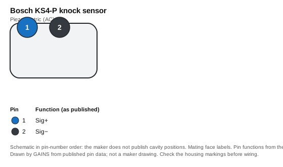
| Pin | Function (as published) | Typical ECU input | Wire note |
|---|---|---|---|
| 1 | Sig+ | Knock input + | Twisted, shielded pair |
| 2 | Sig− | Knock input − (or sensor ground) | Twisted, shielded pair |
Pin functions as published.1 The ECU-input and wire columns are our general guidance, not the maker's.
Connector: Integrated 2-pin (RB-Kp.1 or Jetronic mating); mating part F02U.B00.966-01 (RB-Kp.1) / D261.205.288-01 (Jetronic)1 Connector library
Terminals and seals: Not listed: the Bosch data sheet gives the mating housing only, not contact or seal part numbers.
Native support across ECUs
| ECU platform | Status | How to set it up | Source |
|---|---|---|---|
| GAINS ECU2Concept | Configurable (generic input) | KNOCK (pin 16) on the ECU2; the ECU2 lists two knock inputs. Concept hardware. | Medium27 |
| Haltech (Elite / Nexus) | Configurable (generic input) | One of 2 knock inputs (Nexus R3). | 8 |
| Link (G4X) | Configurable (generic input) | One of 2 knock inputs (G4X FuryX). | 9 |
| MoTeC (M1) | Configurable (generic input) | One of 4 knock inputs (M150). | 10 |
| ECUMaster (EMU Black) | Configurable (generic input) | One of 2 knock inputs. | 11 |
| AEM (Infinity) | Configurable (generic input) | 2-channel knock input. | 12 |
| MaxxECU | Configurable (generic input) | One of 2 knock inputs (RACE). | 13 |
| Holley (Terminator X / EFI) | Configurable (generic input) | One of 2 knock inputs. Holley notes knock control is not enabled in the Terminator X starting configuration. | 14 |
Third-party rows come only from each vendor's public product pages, sensor lists and spec sheets, retrieved on the dates listed in Sources; we do not use ECU software, help files, base maps or calibration files, and reproduce no vendor calibration values. "Preset listed" means the vendor publicly names this sensor; "Configurable" means a matching generic input is listed. Check the vendor's current documentation before buying.
Trademarks belong to their owners. Names are used only to identify compatible products; no endorsement is implied.
CAD and drawings
- Data sheetKnock Sensor KS4-P data sheet 69010059 (PDF)1Download from Bosch MotorsportNo login at last check; the maker may change this
- 3D CAD3D data (zip)56Download from Bosch MotorsportNo login at last check; the maker may change this
We link to the maker's own downloads and do not rehost their CAD or data sheets: the maker's terms do not grant redistribution. Registration may be needed on the maker's site.
Wiring and installation
Clean, machined contact surface; the sensor body rests on the brass compression sleeve; route the cable so it cannot resonate.1
Use a shielded twisted pair to the ECU with the drain at the ECU end only.Medium42
Failure modes and checks
Likely cause Torque or mounting surface changed
Check Re-torque to 20 ± 5 N·m on a clean surface.Medium1
Likely cause Washer or paint between sensor and block
Check Remove anything between sleeve and block; the sensor must rest on its sleeve.Medium1
Test it with a multimeter
- Unplugged, the sensor reads as an open circuit on an ohmmeter (maker: > 1 MΩ; 1,150 ± 200 pF). A low reading points to a damaged sensor or harness.1
Frequently asked
Related
Use it with GAINS
Bosch KS4-P knock sensor on GAINS hardware
GAINS hardware is pre-release concept design; pin numbers can change before release and none of it has been tested on a vehicle yet.23
Concept Pre-release hardware. Pin assignments come from the current design documents and may change.
Sources
14 sources
- Knock Sensor KS4-P data sheet 69010059 · Bosch Motorsport (Bosch Engineering GmbH) · vendor-doc · retrieved 2026-10-27
- internal GAINS internal: ECU2 concept and pin map v0.3 (hardware/mini-ecu/CONCEPT.md §3)
- internal GAINS internal: PDM2 input and output specification (hardware/mini-pdm/SPEC.md)
- Shielded cable · Wikipedia · reference · retrieved 2026-10-27
- KS4 P product page · Bosch Motorsport · vendor-doc · retrieved 2026-10-27
- Bosch Motorsport legal notice · Bosch Motorsport (Robert Bosch GmbH) · vendor-doc · retrieved 2026-10-27
- internal GAINS internal: ECU2 concept (hardware/mini-duo/CONCEPT.md §2)
- Nexus R3 VCU (HT-193000) product page · Haltech · vendor-doc · retrieved 2026-10-27
- G4X FuryX product page · Link Engine Management · vendor-doc · retrieved 2026-10-27
- M150 product page (M1 series) · MoTeC · vendor-doc · retrieved 2026-10-27
- EMU Black product page · ECUMaster · vendor-doc · retrieved 2026-10-27
- Infinity Series 5 hardware specification · AEM Electronics · vendor-doc · retrieved 2026-10-27
- MaxxECU RACE product page · MaxxECU · vendor-doc · retrieved 2026-10-27
- HP / Dominator EFI wiring manual 199R10555 · Holley · vendor-doc · retrieved 2026-10-27
Not yet indexed: fewer than 3 FAQs.