

Engine: M50 / M52 / S50 / S52
Part of the BMW M50 / M52 / M54 family.
Modeled power and torque
Modelled estimate, not a dyno result.
Modeled estimate, not a dyno measurement. Real results vary with fuel, weather, dyno type and build.
Stock is anchored to the factory rating (190 hp at 5500 rpm, 207 lb-ft at 3950 rpm); the curve shape between peaks is modeled. Intake + exhaust + tune (pump fuel): Typical NA gains come mostly above mid-rpm.
M50 / M52 / S50 / S52 data
- Load sensing
- MAF (hot-wire / hot-film)
- O2 sensor
- narrowband (Siemens pre-cat sensors on MS41; described as varying in resistance - element type not stated)
- Closed loop
- narrowband closed loop (ECM corrects injection time); open loop under load not described
- Block
- M50, S50, S52 and North-American M52: cast iron; RoW M52 (and US Z3 M52B28): aluminium
- Rods / pistons
- Not yet sourced
- Reported limit
- ~450-500 hp on stock rotating assembly with an upgraded head gasket (tuning-blog/forum consensus; low confidence)
- Factory
- Bosch EV1 top-feed
- Impedance
- high (saturated)
- Direct-fit upgrades
- 13 maker-listed
- Knock
- BMW 12141703276 (M52/S52 US: 323i/328i/528i/M3/Z3) | 12141738667 (M50/S50: 325i/525i/M3)
- MAP / MAF
- hot-film air mass meter (HFM)
- O2 (upstream)
- narrowband zirconia heated (Siemens, resistive type)
Factory ECU pinout
Each connector face drawn from the OEM service manual's pin data, with every terminal's function and wire colour where the manual prints it.
BMW Siemens MS41.1 DME (E36 328i M52, 88-pin)
The Siemens MS41.1 DME is the engine control module of the M52 six-cylinder in the E36 328i (with the E39 and Z3 M52 cars also on MS41.1 per BMW training). It uses a single 88-pin harness connector, X6000. This page transcribes BMW's 1996 E36 wiring manual: all 88 cavities with function, wire colour and the connector face layout.
1996 model year (pinout as documented); MS41.1 production 1996-1999 per BMW training · US (BMW of North America manual) · 1 connector, 88 cavities · 88 terminals sourced
Looking into the harness plug's mating face (mirror of the ECU face).
How the OEM figure is oriented
BMW's figure (Connector Views 8500.0-06, Fig. 1, B880001.00) is not labelled with a viewing side. It draws pin 28 top-left, 1 top-right, 55 middle-left, 29 middle-right, 88 bottom-left and 56 bottom-right, with a lever/extension at the left and latch tabs at the right. The figure carries BMW's female-terminal (socket) icon, which indicates the harness-side plug; whether the face is the mating face or the wire side is not stated, so it is stored here as the harness plug as drawn. Check the numbers moulded on the housing before wiring.| Pin | Function | Type | Wire | Notes |
|---|---|---|---|---|
| 1 | Cyl. 2 ignition coil control | coil primary drive (ignition output stage inside the DME) | SW/RT (1.5 mm²) | |
| 2 | Cyl. 4 ignition coil control | coil primary drive (ignition output stage inside the DME) | SW/BL (1.5 mm²) | |
| 3 | Cyl. 6 ignition coil control | coil primary drive (ignition output stage inside the DME) | SW/VI (1.5 mm²) | |
| 4 | Ground (ground point) | DME power ground | BR (2.5 mm²) | ETM schematic 1210.17-05 joins pins 4, 32 and 34 at ground X6454. |
| 5 | Cyl. 2 fuel injection valve control | low-side injector driver | BR/RT (0.75 mm²) | Injectors are fed from the DME relay (RT/WS) via splice X6820; the DME switches the ground side. |
| 6 | Cyl. 1 fuel injection valve control | low-side injector driver | BR/WS (0.75 mm²) | |
| 7 | Ground, hot film air mass meter | sensor ground | SW (0.5 mm²) | Hot film air mass meter B6207 pin 4. |
| 8 | Hot film air mass meter signal | analog voltage input | GE (0.5 mm²) | Hot film air mass meter B6207 pin 2; the meter is powered from the DME relay (RT/WS) on its pin 3. |
| 9 | Ti-measurement signal (fuel consumption) to instrument cluster | injection-time (Ti) pulse to the cluster | WS/SW (0.5 mm²) | The ETM pin table lists type E (input); schematic 1210.17-09 draws it as a DME output stage labelled TI feeding instrument cluster X16 pin 21 (fuel consumption). |
| 10 | Engine coolant temperature | NTC thermistor input | BR/RT (0.5 mm²) | Dual temperature sensor B6236 pin 3 (DME element); pin 4 shares the GR/BR ground with intake air temperature (pin 39). |
| 11 | Fuel tank pressure | analog voltage input | GE/RT (0.5 mm²) | Fuel tank pressure sensor B72 pin 3; OBD II leak diagnosis. |
| 12 | Throttle position signal | potentiometer input | SW (0.5 mm²) | Throttle position sensor R6252 pin 2. |
| 13 | Not used | Other / not used | — | |
| 14 | Intake air temperature | NTC thermistor input | GR (0.5 mm²) | Intake air temperature sensor B6205 pin 1. |
| 15 | Speed signal, right rear (from ABS/ASC control module) | wheel-speed pulse input | BR/RT (0.5 mm²) | Colour changes at X20 pin 9: WS/GR/GE on the ABS/ASC side (X1171 pin 15). |
| 16 | Activate A/C (A/C pressure switch) | switch input | SW/GR (0.5 mm²) | Pressure switch B9508 via X10261; also wired to normal speed relay K21. |
| 17 | Not used | Other / not used | — | |
| 18 | Drive-away protection signal (code), EWS II | immobiliser code input | GN (0.5 mm²) | Electronic immobilizer control module A636 (EWS II) X1659 pin 4; 0.35 GN on the EWS side of X20. |
| 19 | A/C-ON signal (air conditioning operating unit) | digital input from climate control | VI/GR (0.5 mm²) | Automatic climate control module A115 X1527 pin 10. |
| 20 | "Check engine" indicator control | lamp driver | GR (0.5 mm²) | To instrument cluster X18 pin 16. |
| 21 | Camshaft control (variable camshaft control valve, VANOS) | solenoid driver | GN/BL (0.5 mm²) | Variable camshaft control valve 1 Y6275 pin 2; valve fed from DME relay (RT/WS). |
| 22 | Cyl. 3 fuel injection valve control | low-side injector driver | BR/GE (0.75 mm²) | |
| 23 | Cyl. 6 fuel injection valve control | low-side injector driver | BR/VI (0.75 mm²) | |
| 24 | Cyl. 4 fuel injection valve control | low-side injector driver | BR/BL (0.75 mm²) | |
| 25 | Oxygen sensor heating ground, sensor I in front of catalytic converter | heater low-side driver | BR (0.5 mm²) | Oxygen sensor B62101 pin 1; heater fed from the DME relay (RT/WS) on pin 3. |
| 26 | Battery voltage (B+ jump start junction point) | 12 V permanent (terminal 30) | RT (0.5 mm²) | |
| 27 | Activate valve, idle speed control valve | idle valve winding driver | WS/GN (0.5 mm²) | Idle speed control valve Y6130 pin 1; pins 27 and 53 drive the valve's two windings (common feed RT/WS on pin 2). |
| 28 | Ground (ground point) | DME ground | — | The schematic draws this ground dashed to Ground Distribution 0670.4; no colour is printed on the MS41.1 pages. |
| 29 | Cyl. 1 ignition coil control | coil primary drive (ignition output stage inside the DME) | SW/WS (1.5 mm²) | Coil-primary wires run in shield W6165 up to 10 mm before the coil connector. |
| 30 | Cyl. 3 ignition coil control | coil primary drive (ignition output stage inside the DME) | SW/GE (1.5 mm²) | |
| 31 | Cyl. 5 ignition coil control | coil primary drive (ignition output stage inside the DME) | SW/GN (1.5 mm²) | |
| 32 | Ground (ground point) | DME power ground | BR (2.5 mm²) | |
| 33 | Cyl. 5 fuel injection valve control | low-side injector driver | BR/GN (0.75 mm²) | |
| 34 | Ground (ground point) | DME power ground | BR (2.5 mm²) | |
| 35 | Activate relay, secondary air pump relay | relay coil driver | BR/GN (0.5 mm²) | Secondary air pump relay K6304 pin 4. |
| 36 | Crankshaft RPM speed signal TD (to instrument cluster) | engine-speed (TD) output | SW (0.5 mm²) | Schematic 1210.17-07 also branches TD (via X1047 / X8015) to the climate control module, cruise control, EWS II, ABS/ASC and data link connector X6002 pin 1. |
| 37 | Not used | Other / not used | — | |
| 38 | Ground, knock sensor shield | shield ground | — | Shield W9110; no wire colour printed. |
| 39 | Ground, temperature sensors | sensor ground | GR/BR (0.5 mm²) | Splice X8038 to intake air temperature B6205 pin 2 and coolant temperature B6236 pin 4. |
| 40 | Ground, crankshaft position/RPM sensor and fuel tank pressure sensor | sensor ground | BR/SW (0.75 mm²) | Splice X6475 also feeds fuel tank pressure sensor ground (0.5 BR/SW). |
| 41 | Ground, camshaft position sensor shield | shield ground | — | Shield W6204 up to 10 mm before the camshaft sensor. |
| 42 | Ground, throttle position sensor | sensor ground | BR (0.5 mm²) | Throttle position sensor R6252 pin 1. |
| 43 | Camshaft position | camshaft sensor signal | BR (0.35 mm²) | Camshaft position sensor B6204 (cylinder identification) pin 3. |
| 44 | Voltage supply, throttle position sensor and fuel tank pressure sensor | 5 V sensor supply | RT/GN (0.5 mm²) | The schematic labels the supply 5V (15); Throttle position sensor R6252 pin 3, and via a splice to fuel tank pressure sensor B72 pin 1. |
| 45 | Throttle position signal (to ABS/ASC control module) | throttle signal output | WS/GR/GE (0.5 mm²) | ABS/ASC X1171 pin 28 via X69 pin 5. |
| 46 | Ti-measurement signal (fuel consumption), instrument cluster | cluster signal | GN/RT (0.5 mm²) | Pin table connection: instrument cluster. Schematic 1210.17-10 shows this wire to instrument cluster X17 pin 13. |
| 47 | Not used | Other / not used | — | |
| 48 | Voltage supply, crankshaft position/RPM sensor | sensor supply | GE (0.5 mm²) | Crankshaft sensor B6203 pin 1; voltage not printed in the pin table. |
| 49 | Terminal 15 (ignition switch) | 12 V switched (terminal 15) | GN (0.5 mm²) | |
| 50 | Running losses solenoid valve | solenoid driver | GE/BL (0.5 mm²) | Solenoid valve Y6550 ("running losses") pin 2. |
| 51 | Activate valve, carbon canister valve | solenoid driver | GN/BL (0.5 mm²) | Carbon canister valve Y199 pin 1 (OBD II page 1210.17-10). |
| 52 | Signal, exhaust flap (exhaust gas flap valve) | solenoid driver | GR/VI (0.5 mm²) | Exhaust gas flap valve Y198. |
| 53 | Activate valve, idle speed control valve | idle valve winding driver | WS/GE (0.5 mm²) | Idle speed control valve Y6130 pin 3 (second winding). |
| 54 | Battery voltage, terminal 87 (engine control module relay) | 12 V from DME relay (terminal 87) | RT/WS (0.5 mm²) | |
| 55 | Oxygen sensor heating ground, sensor II in front of catalytic converter | heater low-side driver | BR (0.5 mm²) | Oxygen sensor B62201 pin 1. |
| 56 | Ground (ground point) | DME ground | — | Listed as an ECM ground in BMW training ST055; no colour found on the MS41.1 schematic pages. |
| 57 | Cyl. 1-3 knock sensor | knock sensor input | GE (0.5 mm²) | Knock sensor B6240 pin 1; shielded (W9110). |
| 58 | Cyl. 1-3 knock sensor | knock sensor input | SW (0.5 mm²) | Knock sensor B6240 pin 2. |
| 59 | Cyl. 4-6 knock sensor | knock sensor input | GN (0.5 mm²) | Knock sensor B6240 pin 3. |
| 60 | Programming voltage (data link connector) | programming voltage input (PGSP) | GN/BL (0.5 mm²) | Data link connector X6002 pin 18 via splice X6860; also to EGS. |
| 61 | Oxygen sensor heating ground, sensor II behind catalytic converter | heater low-side driver | BR (0.5 mm²) | Oxygen sensor B62202 pin 1. |
| 62 | Activate valve, secondary air pump valve | solenoid driver | BR/WS (0.5 mm²) | Secondary air pump valve Y6163 pin 1 (the ETM table prints "value"). |
| 63 | Cyl. 4-6 knock sensor | knock sensor input | BR (0.5 mm²) | Knock sensor B6240 pin 4. |
| 64 | Ground, camshaft position sensor | sensor ground | SW (0.35 mm²) | Camshaft sensor B6204 pin 2. |
| 65 | Camshaft position | camshaft sensor signal | GE (0.35 mm²) | Camshaft sensor B6204 pin 1. |
| 66 | Not used | Other / not used | — | |
| 67 | Oxygen sensor signal ground, sensor I in front of catalytic converter | O2 signal ground | SW (0.5 mm²) | Oxygen sensor B62101 pin 2. |
| 68 | Activate valve, evaporative emission valve | solenoid driver | BR (0.5 mm²) | Evaporative emission valve Y6120 pin 2. |
| 69 | Activate relay, fuel pump relay | relay coil driver | BR/GN (0.5 mm²) | Fuel pump relay K6301 pin 4. |
| 70 | Oxygen sensor signal ground, sensor II in front of catalytic converter | O2 signal ground | SW (0.5 mm²) | Oxygen sensor B62201 pin 2. |
| 71 | Oxygen sensor signal ground, sensor I behind catalytic converter | O2 signal ground | SW (0.5 mm²) | Oxygen sensor B62102 pin 2. |
| 72 | Oxygen sensor signal ground, sensor II behind catalytic converter | O2 signal ground | SW (0.5 mm²) | Oxygen sensor B62202 pin 2. |
| 73 | Activate relay, engine control module relay | relay coil driver | BR (0.5 mm²) | Engine control module relay K6300 pin 85 (X6300 pin 4). The ETM pin table lists type E; the schematic draws it as the DME switching the relay coil to ground. |
| 74 | Activate A/C compressor (compressor control relay) | relay coil driver | SW/BL (0.5 mm²) | Compressor control relay K19 pin 85 (X51 pin 5). |
| 75 | Oxygen sensor I signal, in front of catalytic converter | O2 sensor signal | GE (0.5 mm²) | Oxygen sensor B62101 pin 4. |
| 76 | Oxygen sensor II signal, in front of catalytic converter | O2 sensor signal | GE (0.5 mm²) | Oxygen sensor B62201 pin 4. |
| 77 | Oxygen sensor I signal, behind catalytic converter | O2 sensor signal | GE (0.5 mm²) | Oxygen sensor B62102 pin 4. |
| 78 | Oxygen sensor II signal, behind catalytic converter | O2 sensor signal | GE (0.5 mm²) | Oxygen sensor B62202 pin 4. |
| 79 | Oxygen sensor heating ground, sensor I behind catalytic converter | heater low-side driver | BR (0.5 mm²) | Oxygen sensor B62102 pin 1. |
| 80 | ASC signal ZA (slip control module ABS/ASC) | traction-control interface | WS/GN (0.5 mm²) | ABS/ASC X1171 pin 4 via X69 pin 6. |
| 81 | ASC signal ZWV (slip control module ABS/ASC) | traction-control interface | WS/GR (0.5 mm²) | ABS/ASC X1171 pin 25 via X69 pin 7. |
| 82 | ASC signal MSR (slip control module ABS/ASC) | traction-control interface | WS/RT/GE (0.5 mm²) | ABS/ASC X1171 pin 5 via X69 pin 3. |
| 83 | Crankshaft position/RPM sensor signal | crank sensor signal (sensor supplied from pin 48) | SW (0.35 mm²) | Crankshaft sensor B6203 pin 2; shield W6203 to ground X6454. |
| 84 | Not used | Other / not used | — | |
| 85 | CAN LOW (transmission control module EGS) | CAN low | SW (0.35 mm²) | EGS A8500 X8500 pin 85. |
| 86 | CAN HIGH (transmission control module EGS) | CAN high | GE (0.35 mm²) | EGS A8500 X8500 pin 86. |
| 87 | Battery voltage, terminal 87 (engine control module relay) | 12 V from DME relay (terminal 87) | RT/WS (0.5 mm²) | |
| 88 | TxD diagnosis data link | diagnostic serial (TxD 2) | WS/VI/GE (0.5 mm²) | Data link connector X6002 pin 17. |
Our drawing from published pin data; not an OEM drawing. Layout from the OEM face view (medium confidence). Confirm against the factory manual for your exact year and market before cutting or pinning wires.
Coverage, year splits and safety
Scope: the pin table and colours are BMW of North America's 1996 model-year E36 manual (cars built 9/95 to 8/96), section 1210.17 "Engine control system MS41.1 (6-cylinder M52) 328i". Later MS41.1 years were not compared pin by pin; check each wire colour at the connector before cutting.
Year split on the linked catalog row (E36 325i/328i, 1992-99): only the M52 328i uses MS41.1. The same 1996 manual documents the M50 cars on other systems (DME M3.3.1 and MS40), whose 88-pin pinouts differ, so this page does not apply to an M50 325i.
BMW training (ST055) lists MS41.1 for E36, E39 and Z3 with the M52, and MS41.2 for the E36 M3 S52 (1996-1999), all with an 88-pin connector. The MS41.2 pin table was not available from an allowed source for this file, so the E36 M3 catalog row is deliberately not linked; do not assume every M3 pin matches the 328i.
The DME has two oxygen sensors before and two after the catalytic converters (sensors I and II), secondary air injection, running-losses and exhaust-flap valves, single VANOS, a rotary idle valve with two windings (pins 27 and 53) and CAN to the automatic transmission module only. Cars without a given option leave the related cavities empty.
Safety: disconnect the battery before unplugging the DME. BMW's training material recommends testing through the 88-pin adapter (special tool 88 88 6 614 410) rather than probing the connector; never back-probe through the seals with sharp probes.
Harness: wire-in
No plug-and-play harness for the S3 pinout is listed for this vehicle yet. The route is a universal wire-in harness: the factory ECU is removed and each circuit is wired to the new ECU from a pinout. Nothing is written to the factory ECU.
Being researched
We're mapping S3 plug-in and factory-connector adapter harnesses to this application.
Universal flying lead or re-terminated factory harness
Always available: terminate the engine side to ECU2's two Superseal 34 connectors. Universal harness from $405 USD list.
Your GAINS system for this car · pre-release
ECU2 for the 3 Series E36
Planned with the same rules as the configurator for this car's 6 cyl · port injection · cable throttle. The factory ECU is unplugged and replaced; nothing is written to it.
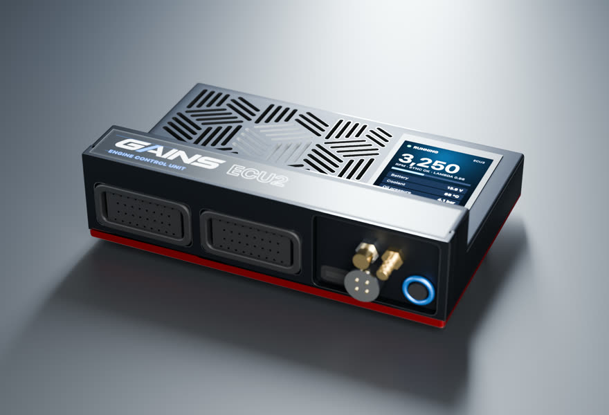
- Price TBA
ECU2Engine controller
6 cyl · port injection · cable throttle
Full sequential fuel and spark for this 6-cylinder on a cable throttle, with the wideband built in.
in designEst. availability: April 2027
Add PDM2 to switch and protect chassis loads (pumps, fans, lights, accessories). Add it in the configurator →
Track days? Add the Telemetry Dongle Pro for 25 Hz GPS lap timing; it plugs into the OBD-II port, and your phone is the dash. Plan it in the configurator →
What you get
- A screen on the ECUA 2.4-inch, 500-nit display in the lid, readable in a footwell.
- Faults in plain words"Coolant temp sensor open circuit.
- S3-style harnessesConnector A and C pin functions follow the published Nexus S3 wiring diagram.
- Powered CAN portA sealed 4-pin port on the insert carries 12 V and CAN for the PDM2 and GAINS displays: one cable per accessory.
- GAINS insideThe on-ECU adaptive layer, the app, logging and your limits.
How it wires in
- Haltech S3 plug-in harnessNone listed for this car
- Factory-connector → S3 adapterNone listed for this car
- Wire-inYour route: universal wire-in harness
Pin-compatible per the published S3 pinout, not yet fit-tested. Every harness option for this car ↓
ECU2 is in design; specifications may change. All GAINS hardware is pre-release concept design; nothing is for sale yet and no application is validated on a vehicle. Harness fitment is from published pinouts and not yet fit-tested.
Swap guides
Into the 3 Series E36
How GAINS approaches the 3 Series E36
Our starting method for this engine, as foundations first: get it running and drivable, then learn fuel, then the hardware-specific strategies. It is a methodology outline, not a validated calibration.
- 1Base map and first startplanned
Start from displacement, injector data and the sensors fitted, then let the first-start learner settle cranking, idle and warm-up before any load work. The goal is a safe, running engine, not a finished calibration.
- 2Lambda targets and VE learningclosed loop on GAINS ECUs
Air-fuel targets come from your goal (street, track, economy). The ECU then learns its fuel table cell by cell from the onboard wideband inside a signed envelope, and you approve promoting what it learned into the base map.
- 3Cam phasing (VVT)gated
Begin with conservative overlap. Cam targets per load cell are then chosen with torque and knock in mind, keeping idle and cold overlap low for stability. Widening cam authority follows the same evidence-gated path as spark.
- 4Drivability foundationsplanned
Pedal map, tip-in and decel fuel, idle control, cold start and warm-up enrichment: the tables tuners spend hours on after the main map. Each is a strategy in the knowledge engine with its own limits.
- 5Factory load sensingfactory reference
What the factory ECU measures load with: MAF (hot-wire / hot-film) (medium confidence)
- 6Wideband sensorhardware
Add a wideband: the factory narrowband only tells rich from lean around stoichiometric, so it cannot close the loop at power or economy targets; fit a Bosch LSU 4.9 for the GAINS ECU's built-in controller
- 7Bottom end and head sealingfactory reference
Reported: On turbo builds the head gasket is usually cited as the first failure, with stock rods/pistons/ring lands becoming a concern around 450-550 hp (tuning blog and forum consensus); aluminium Nikasil M52 is generally regarded as less suited to boost than the iron M50 block. (medium confidence) Limits depend on tune quality, fuel, rpm and condition and are not guaranteed.
GAINS on the 3 Series E36
ECU2
Designed so your phone is the laptop, keypad and dash
The GAINS app is designed to handle tuning, logging, gauges and switch inputs over Bluetooth, so the system needs no separate CAN keypad or display. Keypad, dash and logging views are planned; the iOS prototype runs on simulated data today.
Wideband, IMU and logging built in
An onboard Bosch LSU 4.9 wideband controller, a 6-axis IMU and onboard logging are designed into the ECU rather than sold as add-on modules.
Modular, so you buy what the engine needs
This engine runs on ECU2. PDM2 (power, body and gearbox) is optional and connects over ECU2's powered CAN port; the Telemetry Dongle Pro adds GPS lap timing from the OBD-II port.
Calibration that keeps learning
Instead of a fixed map that drifts as parts and conditions change, the ECU keeps adapting its fuel trims within limits you can see and approve in the app.
Adaptive tuning strategies
- VE learning closed loop on GAINS ECUs
Learns the fuel table from the onboard wideband as you drive, cell by cell, inside a signed authority envelope. Learned trims are promoted into the base map without a step in fuelling.
- Goal-based lambda targets closed loop on GAINS ECUs
Sets air-fuel targets from your goal (economy, response, power, safety margin) instead of a single fixed table.
- Knock protection protection
Listens for knock on a dedicated knock processor, pulls timing at once and restores it slowly. It only ever reduces advance.
- Warm-up, cranking, idle and transient fuel planned
The same learning approach applied to the tables tuners spend hours on after the main map is done.
- Spark advance and boost authority gated
Widening ignition advance or boost is never automatic. It stays an expert or dyno decision until validated knock detection exists for the engine family.
Already running another ECU? In advisor mode the same strategies read your logs and recommend exact table changes with the reasoning, which you apply in your ECU vendor's own software.
GAINS hardware is pre-release concept design. Simulated results only; nothing is validated on a vehicle yet.
Catalog data and evidence
- Catalog data, not yet expert-reviewed.
- No vehicle photos: illustrations only until licensed imagery is available.
- Factory ECU part numbers not yet sourced for this vehicle.
- E-900 Haltech Nexus S3 catalog (sourced, high confidence)
- E-941 S3 engine harness availability (inferred, medium confidence)