

Engine: 4G63T (Evo I-IX)
Part of the Mitsubishi 4G63 family.
Modeled power and torque
Modelled estimate, not a dyno result.
Modeled estimate, not a dyno measurement. Real results vary with fuel, weather, dyno type and build.
Stock is anchored to the factory rating (286 hp at 6500 rpm, 289 lb-ft at 3500 rpm); the curve shape between peaks is modeled. Bolt-ons + tune (pump fuel, more boost): Stock turbo/supercharger; gains limited by compressor and fuel system.
4G63T (Evo I-IX) data
- Load sensing
- MAF (Karman vortex)
- O2 sensor
- Not yet sourced
- Closed loop
- Not yet sourced
- Block
- cast iron
- Rods / pistons
- forged steel (2003 US Evo, Wikipedia)
- Reported limit
- 600+ whp reported on stock blocks (DSPORT; block, not internals)
- Factory
- Top-feed, low-impedance with resistor pack (Evo 8/9)
- Impedance
- low (peak and hold)
- Direct-fit upgrades
- 6 maker-listed
- Knock
- piezo knock sensor
- MAP / MAF
- Karman vortex, frequency (integrated IAT and baro)
- O2 (upstream)
- narrowband zirconia
Platform background
The Evo IV introduced the CN9A body, the engine and transaxle rotated relative to the Evo III, a twin-scroll turbo, a crank-mounted crank angle sensor and plug-top coils. The Evo V and VI (CP9A) carried the same engine management with MDL560 injectors, an O2 sensor heater, and (Evo VI) two-speed fan and fuel pump control. The Evo VI workshop manual documents the engine-ECU terminal assignments for all three cars. That makes this one of the best-documented 4G63T platforms for a plug-in or reflash conversion.
Factory ECU
Mitsubishi Engine-ECU, Karman vortex airflow-based MPI with sequential injection and wasted-spark ignition
Sourced12MUT-II scan tool with actuator tests. The Evo VI added actuator tests for the secondary air solenoid and condenser fan high/low.
Sourced1The Evo IV-VI ECU reads a Karman vortex airflow sensor (with built-in IAT and baro), a crank-mounted crank angle sensor, a stick-type cam sensor, a knock sensor, a narrowband O2 sensor, TPS plus idle switch, and an exhaust high-temperature sensor. It drives four low-impedance injectors, two coil/power transistor units (1/4 and 2/3), a stepper IAC, the wastegate solenoid, the hot-start fuel pressure control valve and the secondary air solenoid. The terminal list below shows the full set of inputs and outputs.
Factory ECU: harness cross-reference
From the factory ECU each listed harness plugs into. The factory ECU is unplugged, not modified. Check the label and part number on your own ECU before ordering.
- ECU family
- Mitsubishi MD-series ECU, E2T case codes (e.g. E2T67380)
- Applies to
- Evo IV-VIII 5-speed all regions; Evo VIII MR USDM; Eclipse/Talon 2G turbo USDM; manual
- Not for
- not 6-speed JDM Evo VIII MR or Evo IX (use HT-186360); not automatic
- Supplier
- Mitsubishi Electric
Examples only: MD334794 (case E2T67380) listed as Evo IV; MD356472 as Evo IV-VI GSR. Evo VII/VIII and 2G Eclipse numbers not confirmed. Harness spans several ECU generations.
- ECU family
- Mitsubishi Lancer Evolution IV-V ECU
- Applies to
- 1996-1999 Evo IV, V, manual; JDM
No OEM number found; one SKU spans Evo IV-V.
- ECU family
- Mitsubishi Lancer Evolution VI ECU
- Applies to
- 1999-2000 Evo VI, manual; JDM
No OEM number found.
Factory ECU pinout
Each connector face drawn from the OEM service manual's pin data, with every terminal's function and wire colour where the manual prints it.
Mitsubishi Lancer Evolution IV-VI engine-ECU (4G63T)
The Mitsubishi Lancer Evolution IV-VI engine-ECU (4G63T) uses 1 connector with 76 cavities. This page draws each face from the OEM figure and lists the 51 terminals the OEM table documents, with wire colours where the manual prints them.
1996-2001 (Evo VI manual) · Japan / export · 1 connector, 76 cavities · 51 terminals sourced
Looking into the harness plug's mating face (mirror of the ECU face).
How the OEM figure is oriented
Harness side (looking into the plug), as drawn in the OEM figure.| Pin | Function | Type | Wire | Notes |
|---|---|---|---|---|
| 1 | No.1 injector (low side) | Injector | — | |
| 2 | No.3 injector | Injector | — | |
| 3 | Fuel pressure control valve (hot-start solenoid) | Outputs | — | |
| 4 | ISC stepper motor coil A1 | Outputs | — | |
| 5 | ISC stepper motor coil B1 | Outputs | — | |
| 6 | Secondary air control solenoid valve | Outputs | — | |
| 8 | Fuel pump relay | Outputs | — | |
| 10 | Power transistor unit A (ignition, cylinders 1/4) | Ignition | — | |
| 11 | Wastegate solenoid valve | Outputs | — | |
| 12 | Power supply (from control relay) | Outputs | — | |
| 13 | ECU earth | Ground | — | |
| 14 | No.2 injector | Injector | — | |
| 15 | No.4 injector | Injector | — | |
| 17 | ISC stepper motor coil A2 | Outputs | — | |
| 18 | ISC stepper motor coil B2 | Outputs | — | |
| 19 | Air flow sensor reset signal | Sensor signal | — | |
| 20 | Fan motor relay HI (radiator fan relay HI on Evo VI) | Outputs | — | |
| 21 | Fan motor relay LOW (radiator fan relay LOW on Evo VI) | Outputs | — | |
| 22 | A/C relay | Outputs | — | |
| 23 | Power transistor unit B (ignition, cylinders 2/3) | Ignition | — | |
| 25 | Power supply (from control relay) | Outputs | — | |
| 26 | ECU earth | Ground | — | |
| 32 | A/C condenser fan motor relay HI (Evo VI) | Outputs | — | |
| 33 | Alternator G terminal | Outputs | — | |
| 34 | A/C condenser fan motor relay LOW (Evo VI) | Outputs | — | |
| 36 | Engine warning lamp | Outputs | — | |
| 37 | Power steering fluid pressure switch | Sensor signal | — | |
| 38 | Control relay (ECU-switched main relay) | Outputs | — | |
| 39 | Fuel pump relay No.2 (pump speed) | Outputs | — | |
| 40 | Exhaust temperature warning lamp | Outputs | — | |
| 44 | Alternator FR terminal | Sensor signal | — | (medium confidence) |
| 45 | A/C switch | Sensor signal | — | |
| 60 | Oxygen sensor heater (Evo V, VI) | Outputs | — | |
| 71 | Ignition switch ST (cranking) | Sensor signal | — | |
| 72 | Intake air temperature sensor | Sensor signal | — | |
| 74 | High temperature (exhaust) sensor circuit, measured 74-77 | Sensor signal | — | (medium confidence) |
| 76 | Oxygen sensor signal | Sensor signal | — | |
| 77 | High temperature (exhaust) sensor circuit, measured 74-77 | Sensor signal | — | (medium confidence) |
| 80 | Backup power supply (battery) | Power | — | |
| 81 | Sensor supply voltage (4.5-5.5 V) | Sensor 5 V / ground | — | |
| 82 | Ignition switch IG | Power | — | |
| 83 | Engine coolant temperature sensor | Sensor signal | — | |
| 84 | Throttle position sensor | Sensor signal | — | |
| 85 | Barometric pressure sensor | Sensor signal | — | |
| 86 | Vehicle speed sensor | Sensor signal | — | |
| 87 | Idle position switch | Sensor signal | — | |
| 88 | Camshaft position sensor | Crank / cam | — | |
| 89 | Crank angle sensor | Crank / cam | — | |
| 90 | Air flow sensor signal | Sensor signal | — | |
| 91 | Earth (continuity to body specified) | Ground | — | (medium confidence) |
| 92 | Sensor earth (reference for IAT, ECT and idle switch checks) | Sensor 5 V / ground | — | (medium confidence) |
Our drawing from published pin data; not an OEM drawing. Layout from the OEM face view (high confidence). Confirm against the factory manual for your exact year and market before cutting or pinning wires.
Coverage, year splits and safety
Transcribed from the Lancer Evolution VI workshop manual, Group 13 MPI. Evo IV and V ECUs are closely related but were not checked against their own manuals; confirm before wiring.
Source notes: From the Lancer Evolution VI workshop manual, Group 13 MPI troubleshooting (engine-ECU terminal voltage and harness resistance tables). Where rows apply to only Evo IV/V or VI, the manual says so and that is noted. The scanned pages were read by OCR. Wire colours are not given in these tables. Unlisted terminals are unused or not in the check tables; verify with a meter.
Safety: disconnect the battery before working on the ECU harness, and confirm each terminal with a meter against your own car's manual before cutting or pinning wires.
Plug-and-play harness
A plug-in harness built for the Haltech Nexus S3 pinout is listed for this vehicle. The ECU2 follows that published pinout, so the factory ECU is unplugged and the ECU2 plugs into the car's own loom. Nothing is written to the factory ECU. Pin-compatible per the published S3 pinout, not yet fit-tested.
| Maker | Harness | Fits | Link | |
|---|---|---|---|---|
 | Mitsubishi EVO 4-8 & 2GHT-186332 | Evo IV-VIII 5-speed all regions; Evo VIII MR USDM; Eclipse/Talon 2G turbo USDM; manual | $535Lowest | Maker ↗ |
 | Manual 1998 - 1999 Mitsubishi EVO VBF29121-S3 | 1996-1999 Evo IV, V, manual; JDM | $840 | Maker ↗ |
| Manual 1999 - 2000 Mitsubishi EVO VIBF29122-S3 | 1999-2000 Evo VI, manual; JDM | $840 | Maker ↗ |
| Wire-in | Universal flying lead or re-terminated factory harness | Any engine (terminate to ECU2's two Superseal 34 connectors) | Universal harness from $405 | Maker ↗ |
Nexus S3 Plug n Play Adapter Harness Mitsubishi EVO 4-8 & 2G
- Plugs into
Mitsubishi 4G63T ECU (Evo IV-VIII / Eclipse 2G Turbo) · MD334794, MD356472
- OEM part numbers
- MD334794, MD356472
- ECU
- Mitsubishi Electric · Mitsubishi MD-series ECU, E2T case codes (e.g. E2T67380)
- Confidence
- low
Examples only: MD334794 (case E2T67380) listed as Evo IV; MD356472 as Evo IV-VI GSR. Evo VII/VIII and 2G Eclipse numbers not confirmed. Harness spans several ECU generations.
Sources: E-1443
- Fits
- Evo IV-VIII 5-speed all regions; Evo VIII MR USDM; Eclipse/Talon 2G turbo USDM; manual
- Exclusions
- not 6-speed JDM Evo VIII MR or Evo IX (use HT-186360); not automatic
- SKU
- HT-186332
- Maker fitment
- Mitsubishi EVO 4-8 (5-speed, all regions), EVO 8 MR (USDM), Eclipse 2G Turbo (USDM); manual only
- Maker notes
- kit HT-213308
Boomslang plug-and-play harness for Haltech Nexus S3 - Manual 1998 - 1999 Mitsubishi EVO V
- Plugs into
ECU (4G63T, Evo IV-V, CN9A/CP9A)
- ECU
- Mitsubishi Lancer Evolution IV-V ECU
- Confidence
- low
No OEM number found; one SKU spans Evo IV-V.
- Fits
- 1996-1999 Evo IV, V, manual; JDM
- SKU
- BF29121-S3
- Maker fitment
- Mitsubishi EVO IV; Mitsubishi EVO V (Manual); selector years 1996-1999; SKU label: Manual 1998 - 1999 Mitsubishi EVO V
- Maker notes
- separate SKUs exist for other Nexus models (-S2/-R3/-R5/-T1/-T2); EVO IV-V
Boomslang plug-and-play harness for Haltech Nexus S3 - Manual 1999 - 2000 Mitsubishi EVO VI
- Plugs into
ECU (4G63T, Evo VI / TME, CP9A)
- ECU
- Mitsubishi Lancer Evolution VI ECU
- Confidence
- low
No OEM number found.
- Fits
- 1999-2000 Evo VI, manual; JDM
- SKU
- BF29122-S3
- Maker fitment
- Mitsubishi EVO VI (Manual); selector years 1999-2000; SKU label: Manual 1999 - 2000 Mitsubishi EVO VI
- Maker notes
- separate SKUs exist for other Nexus models (-S2/-R3/-R5/-T1/-T2); EVO VI
Haltech and Boomslang are trademarks of their respective owners. GAINS is not affiliated with or endorsed by them.
Your GAINS system for this car · pre-release
ECU2 for the Lancer Evolution IV-VI
Planned with the same rules as the configurator for this car's 4 cyl · port injection · cable throttle. The factory ECU is unplugged and replaced; nothing is written to it.
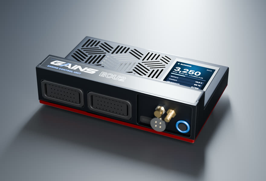
- Price TBA
ECU2Engine controller
4 cyl · port injection · cable throttle
Full sequential fuel and spark for this 4-cylinder on a cable throttle, with the wideband built in.
in designEst. availability: April 2027
Add PDM2 to switch and protect chassis loads (pumps, fans, lights, accessories). Add it in the configurator →
Track days? Add the Telemetry Dongle Pro for 25 Hz GPS lap timing; it plugs into the OBD-II port, and your phone is the dash. Plan it in the configurator →
What you get
- A screen on the ECUA 2.4-inch, 500-nit display in the lid, readable in a footwell.
- Faults in plain words"Coolant temp sensor open circuit.
- S3-style harnessesConnector A and C pin functions follow the published Nexus S3 wiring diagram.
- Powered CAN portA sealed 4-pin port on the insert carries 12 V and CAN for the PDM2 and GAINS displays: one cable per accessory.
- GAINS insideThe on-ECU adaptive layer, the app, logging and your limits.
How it wires in
- Haltech S3 plug-in harness1 listed · from $535 USD listHT-186332
- Factory-connector → S3 adapter2 listed · from $840 USD list
- Wire-inAlways possible
Pin-compatible per the published S3 pinout, not yet fit-tested. Every harness option for this car ↓
ECU2 is in design; specifications may change. All GAINS hardware is pre-release concept design; nothing is for sale yet and no application is validated on a vehicle. Harness fitment is from published pinouts and not yet fit-tested.
How GAINS approaches the Lancer Evolution IV-VI
Our starting method for this engine, as foundations first: get it running and drivable, then learn fuel, then the hardware-specific strategies. It is a methodology outline, not a validated calibration.
- 1Base map and first startplanned
Start from displacement, injector data and the sensors fitted, then let the first-start learner settle cranking, idle and warm-up before any load work. The goal is a safe, running engine, not a finished calibration.
- 2Lambda targets and VE learningclosed loop on GAINS ECUs
Air-fuel targets come from your goal (street, track, economy). The ECU then learns its fuel table cell by cell from the onboard wideband inside a signed envelope, and you approve promoting what it learned into the base map.
- 3Cam phasing (VVT)gated
Begin with conservative overlap. Cam targets per load cell are then chosen with torque and knock in mind, keeping idle and cold overlap low for stability. Widening cam authority follows the same evidence-gated path as spark.
- 4Boost controlgated
A closed-loop boost target by gear and goal, held inside the authority envelope, with knock protection active at boost. Raising boost authority is never automatic; it stays an expert or dyno decision.
- 5Drivability foundationsplanned
Pedal map, tip-in and decel fuel, idle control, cold start and warm-up enrichment: the tables tuners spend hours on after the main map. Each is a strategy in the knowledge engine with its own limits.
- 6Factory load sensingfactory reference
What the factory ECU measures load with: MAF (Karman vortex) (medium confidence)
- 7Wideband sensorhardware
factory O2 type not yet sourced; plan on a Bosch LSU 4.9 for the GAINS ECU's built-in controller
- 8Bottom end and head sealingfactory reference
Reported: DSPORT reports the iron block as strong, with hundreds of stock-block examples beyond 600 whp; rods/pistons typically cited first (forum). (medium confidence) Limits depend on tune quality, fuel, rpm and condition and are not guaranteed.
Drivetrain
Chassis integration
ECU-controlled two-speed radiator fan relays (HI/LOW). The Evo VI adds condenser fan HI/LOW relays.
Sourced12Engine warning lamp (36) and exhaust temperature warning lamp (40) are ECU-driven
Sourced1A replacement ECU must keep the control relay (38) logic, the fan and A/C relays, the exhaust temperature warning lamp and the alternator G/FR interface, or the car will show warnings and idle poorly under electrical load. The AYC system on the GSR has its own controller and needs throttle and engine data, so confirm the AYC ECU's inputs before replacing the engine ECU.
Tuning notes
Common first steps are a reflash or piggyback on the factory ECU, then larger injectors and a pump upgrade. Pump upgrades should be wired to bypass the factory low-speed resistor path deliberately. For standalone conversions the factory Hall-type crank and cam sensors can be retained. The airflow sensor is usually replaced with MAP-based load at higher power.
Popular swaps
- Uses the rotated (Evo IV-type) 4G63T. Evo VII-IX parts share this orientation
- Evo I-III and DSM parts do not.
GAINS on the Lancer Evolution IV-VI
ECU2
Designed so your phone is the laptop, keypad and dash
The GAINS app is designed to handle tuning, logging, gauges and switch inputs over Bluetooth, so the system needs no separate CAN keypad or display. Keypad, dash and logging views are planned; the iOS prototype runs on simulated data today.
Wideband, IMU and logging built in
An onboard Bosch LSU 4.9 wideband controller, a 6-axis IMU and onboard logging are designed into the ECU rather than sold as add-on modules.
Modular, so you buy what the engine needs
This engine runs on ECU2. PDM2 (power, body and gearbox) is optional and connects over ECU2's powered CAN port; the Telemetry Dongle Pro adds GPS lap timing from the OBD-II port.
Calibration that keeps learning
Instead of a fixed map that drifts as parts and conditions change, the ECU keeps adapting its fuel trims within limits you can see and approve in the app.
Adaptive tuning strategies
- VE learning closed loop on GAINS ECUs
Learns the fuel table from the onboard wideband as you drive, cell by cell, inside a signed authority envelope. Learned trims are promoted into the base map without a step in fuelling.
- Goal-based lambda targets closed loop on GAINS ECUs
Sets air-fuel targets from your goal (economy, response, power, safety margin) instead of a single fixed table.
- Knock protection protection
Listens for knock on a dedicated knock processor, pulls timing at once and restores it slowly. It only ever reduces advance.
- Warm-up, cranking, idle and transient fuel planned
The same learning approach applied to the tables tuners spend hours on after the main map is done.
- Spark advance and boost authority gated
Widening ignition advance or boost is never automatic. It stays an expert or dyno decision until validated knock detection exists for the engine family.
Already running another ECU? In advisor mode the same strategies read your logs and recommend exact table changes with the reasoning, which you apply in your ECU vendor's own software.
GAINS hardware is pre-release concept design. Simulated results only; nothing is validated on a vehicle yet.
Frequently asked
Where are the injector pins on the Evo 5/6 ECU?
Terminals 1, 14, 2 and 15 drive injectors 1, 2, 3 and 4. Power supply is on 12 and 25, and ECU earth on 13 and 26.1
What injectors does an Evo 5 use?
MDL560 low-impedance injectors (2-3 ohm), up from the Evo IV's MDL510.21
What changed in the Evo IV engine?
The engine and gearbox were rotated relative to the Evo III. The Evo IV also gained a twin-scroll turbo, forged pistons, stronger rods, a new airflow sensor, a crank-mounted crank angle sensor, a stick-type cam sensor, plug-top coils with built-in power transistors and a secondary air system. The ignition timing adjustment connector was deleted.2
Which pins are the crank and cam sensors on an Evo 4-6?
Crank angle sensor on terminal 89, camshaft position sensor on 88, with the 5 V sensor supply on 81.1
Does the Evo 6 have two-speed fuel pump control?
Yes. The Evo VI added fuel pump relay No.2 and a fuel pump resistor, and the ECU switches pump speed through terminal 39.1
Sources
Numbered as cited above. Hover or tap a citation chip to preview it.
- Lancer Evolution VI Workshop Manual, Group 13 Fuel - MPI (engine-ECU terminal voltages; harness resistance and continuity) · Mitsubishi Motors (hosted by EvoScan, archived; scanned, read by OCR) · service-manual · retrieved 2026-10-25
- Lancer Evolution IV / V Technical Information Manual (Pub. N98060NCP9), Engine section · Mitsubishi Motors / Ralliart (hosted by EvoScan, archived; scanned, read by OCR) · oem · retrieved 2026-10-25
- Mitsubishi Lancer Evolution · Wikipedia · community · retrieved 2026-10-25
Catalog data and evidence
- Catalog data, not yet expert-reviewed.
- No vehicle photos: illustrations only until licensed imagery is available.
- E-901 Haltech S3 plug-in harness family (sourced, high confidence)
- E-912 Haltech S3 adapter harness page (sourced, high confidence)
- E-934 Boomslang identity (sourced, high confidence)
- E-935 Boomslang S3 catalog size (sourced, high confidence)
- E-900 Haltech Nexus S3 catalog (sourced, high confidence)
- E-941 S3 engine harness availability (inferred, medium confidence)
- E-1443 Evo IV-VI ECU (reported, low confidence)