

Engines for this swap: the Toyota JZ family
A swap has no factory engine. Pick your donor below; each links to its own specs, sensors and ECU.
Single-turbo conversion assumed
Platform background
JZ swaps transplant a longitudinal Toyota inline-six (usually 1JZ-GTE or 2JZ-GTE, sometimes a 2JZ-GE converted to turbo) into another RWD chassis. Most swaps assume a single-turbo conversion and a standalone ECU, which removes the factory sequential-turbo VSVs and the need for donor-car body electrics. Key engine-side items are trigger sensors, VVT-i control on later engines, low-impedance injectors on export 2JZ-GTEs, and Toyota's distributor ignition on non-VVT-i 2JZ-GE engines.
Factory ECU
Factory ECUs expect donor-car inputs (speed, A/C, neutral switch, TRAC on Supra, immobilizer on later Lexus/Toyota donors)
Sourced · medium32Sequential 2JZ-GTE ECUs control several turbo VSVs that are deleted in single-turbo conversions
Sourced5Reusing a donor ECU is practical only when the donor harness, ECU and every expected input are transplanted together. For modified engines, a standalone ECU with a purpose-built engine harness is the norm: it needs six injector outputs (with peak-and-hold or the factory resistor pack for low-impedance injectors), ignition outputs matched to the coil/igniter hardware, VR inputs for Toyota pickups, and a VVT-i PWM output and cam position input on VVT-i engines.
Factory ECU: harness cross-reference
From the factory ECU each listed harness plugs into. The factory ECU is unplugged, not modified. Check the label and part number on your own ECU before ordering.
- ECU family
- Toyota 89661-series
- Applies to
- JZX100 Mark II/Cresta/Chaser 1JZ-GTE VVT-i JDM; Soarer JZZ30 MY96-01; manual
- Not for
- non-VVTi 1JZ; automatic; factory TRC/ETCS disabled
- Supplier
- Denso
89661-22790 listed as manual; 89661-22800 listed for JZX100 (transmission unstated); Denso per one listing. JZZ30 numbers not gathered.
- ECU family
- Toyota 89661-series
- Applies to
- JZA80 Supra 2JZ-GTE/GE non-VVTi (1993-97); manual
- Not for
- VVT-i JZA80 (1997+); automatic
No source-supported part number. Non-VVTi vs VVTi electronics differ significantly.
- ECU family
- Toyota 1JZ-GTE
- Applies to
- 1991-96 Chaser JZX90 / Soarer JZZ30 manual
- ECU family
- Toyota 1JZ-GTE VVT-i
- Applies to
- 1997-2001 manual
Listings mention 89661-22790/-22800 for JZX100 (not registered).
- ECU family
- Toyota 2JZ-GE VVT-i
- Applies to
- 1998-2001 Aristo, GS300, IS300, SC300, Supra NA; auto/manual
One SKU across several chassis; ECM codes not verified.
- ECU family
- Toyota 2JZ-GE VVT-i
- Applies to
- 2002-05 GS300/IS300; 89661-53450 = 2005 IS300 manual example
Listing only; immobiliser-matched.
- ECU family
- Toyota 2JZ-GTE VVT-i
- Applies to
- 1998-2002 Supra Turbo V161 6-speed
Forum-reported, unconfirmed.
- ECU family
- Toyota 1JZ-GTE
- Applies to
- 1991-96 Chaser/Soarer automatic
- ECU family
- Toyota 1JZ-GTE VVT-i
- Applies to
- 1997-2001 automatic
- ECU family
- Toyota 2JZ-GTE VVT-i
- Applies to
- 1998-2002 Supra Turbo A340E auto
Forum-reported, unconfirmed.
- ECU family
- Toyota 2JZ-GTE
- Applies to
- 1993-98 Supra Turbo manual
- Not for
- 1998+ VVT-i cars (separate SKU)
USDM 1998 Turbo was VVT-i; overlap with BF29147 - confirm.
- ECU family
- Toyota 2JZ-GE
- Applies to
- 1992-97 SC300 / 1993-97 Supra NA manual
- ECU family
- Toyota 2JZ-GTE
- Applies to
- 1991-98 Supra/Aristo Turbo automatic
- ECU family
- Toyota 2JZ-GE
- Applies to
- 1992-97 SC300 / Supra NA automatic
Factory ECU pinout
Each connector face drawn from the OEM service manual's pin data, with every terminal's function and wire colour where the manual prints it.
Lexus IS300 2JZ-GE VVT-i ECM (2001-2005, US)
The 2001-05 Lexus IS300 (2JZ-GE VVT-i, drive-by-wire) uses one ECM that also runs the A/T. Toyota changed it after 2001: the 2001 ECM has six plugs, E2 to E7 (148 cavities), and the 2002 ECM has five denser plugs, E3 to E7 (167 cavities), with different terminal numbers. Both are listed here from the Lexus repair manuals and wiring diagrams.
2001-2005 · USA (as documented in the US repair manuals); other markets not verified · 11 connectors, 315 cavities · 227 terminals sourced
Looking into the ECU's connector. The harness plug seen from its wire side has the same layout.
How the OEM figure is oriented
Terminals of ECM figure (RM779U DI-20, art A01888) as printed: the ECM drawn with its six connectors in a row, E7 E6 E5 E4 E3 E2 left to right, latch on top, each connector enlarged below with terminal numbers. Terminal 1 is at the top right of each connector and numbers run right to left. Toyota does not label the face, but the figure depicts the connector bank on the ECM, so it is recorded as ecu-side; confirm against the part before cutting a harness.| Pin | Function | Type | Wire | Notes |
|---|---|---|---|---|
| E2-9 | EOM (OEM symbol; W-B wire joined to the EC ground on the EWD) | ground | W-B | From the EWD only (not in the Terminals of ECM voltage table). (medium confidence) |
| E2-10 | Unlock warning switch input (KSW) | switch input | B-Y | From the EWD only (not in the Terminals of ECM voltage table). |
| E2-13 | VSV, pressure switching valve (TBP) | low-side solenoid driver | P | Listed in both the Terminals of ECM table and the EWD. |
| E2-20 | Security indicator light, via combination meter (IMLD) | lamp driver | L-B | From the EWD only (not in the Terminals of ECM voltage table). |
| E2-21 | Transponder key amplifier, TXCT line (TXCT) | serial | P | From the EWD only (not in the Terminals of ECM voltage table). The RM779U Terminals of ECM table prints the CCV return as "E01 (E2-21)"; the EWD shows E2-21 as TXCT and E01 on E7-21, so that table entry is a misprint. |
| E2-22 | Transponder key amplifier, RXCK line (RXCK) | serial | V | From the EWD only (not in the Terminals of ECM voltage table). |
| E2-23 | Transponder key amplifier, CODE line (CODE) | serial | G | From the EWD only (not in the Terminals of ECM voltage table). |
| E2-24 | Heated oxygen sensor signal (OXR2) | O2 sensor signal | W | Listed in both the Terminals of ECM table and the EWD. |
| E2-25 | Heated oxygen sensor heater control (HTR2) | low-side heater driver | R-W | Listed in both the Terminals of ECM table and the EWD. |
| E2-26 | Heated oxygen sensor heater control (HTL2) | low-side heater driver | G-B | Listed in both the Terminals of ECM table and the EWD. |
Our drawing from published pin data; not an OEM drawing. Layout from the OEM face view (medium confidence). Confirm against the factory manual for your exact year and market before cutting or pinning wires.
Looking into the ECU's connector. The harness plug seen from its wire side has the same layout.
How the OEM figure is oriented
Terminals of ECM figure (RM779U DI-20, art A01888) as printed: the ECM drawn with its six connectors in a row, E7 E6 E5 E4 E3 E2 left to right, latch on top, each connector enlarged below with terminal numbers. Terminal 1 is at the top right of each connector and numbers run right to left. Toyota does not label the face, but the figure depicts the connector bank on the ECM, so it is recorded as ecu-side; confirm against the part before cutting a harness.| Pin | Function | Type | Wire | Notes |
|---|---|---|---|---|
| E3-1 | Battery backup supply (BATT) | 12 V constant | B-Y | Listed in both the Terminals of ECM table and the EWD. |
| E3-4 | Fuel pump relay control, fuel pump resistor bypass (FPR) | relay driver | G-R | Listed in both the Terminals of ECM table and the EWD. |
| E3-5 | Circuit opening relay control (FC) | relay driver | G-Y | Listed in both the Terminals of ECM table and the EWD. |
| E3-6 | Check engine (MIL) warning lamp (W) | lamp driver | R-L | Listed in both the Terminals of ECM table and the EWD. |
| E3-7 | Throttle control motor power supply (+BM) | 12 V constant | L-W | Listed in both the Terminals of ECM table and the EWD. |
| E3-8 | Main supply from EFI relay (+B2) | 12 V switched | B-R | Listed in both the Terminals of ECM table and the EWD. |
| E3-9 | Ignition switch signal (IGSW) | 12 V input (IG ON) | B-O | Listed in both the Terminals of ECM table and the EWD. |
| E3-10 | EFI main relay control (MREL) | relay driver | B-O | Listed in both the Terminals of ECM table and the EWD. |
| E3-11 | Diagnostic serial line to DLC3 (SIL) | serial | W | Listed in both the Terminals of ECM table and the EWD. |
| E3-13 | Traction control link from ABS and traction ECU (TRC+) | Comms / diag | R-Y | From the EWD only (not in the Terminals of ECM voltage table). |
| E3-14 | Engine data link to ABS and traction ECU (ENG+) | Comms / diag | L-B | From the EWD only (not in the Terminals of ECM voltage table). |
| E3-15 | Engine speed output to ABS and traction ECU (NEO) | pulse output | G | From the EWD only (not in the Terminals of ECM voltage table). |
| E3-16 | Main supply from EFI relay (+B) | 12 V switched | B-R | Listed in both the Terminals of ECM table and the EWD. |
| E3-20 | Traction control link from ABS and traction ECU (TRC-) | Comms / diag | W-G | From the EWD only (not in the Terminals of ECM voltage table). |
| E3-21 | Engine data link to ABS and traction ECU (ENG-) | Comms / diag | P | From the EWD only (not in the Terminals of ECM voltage table). |
| E3-22 | ECM case / body ground (EC) | ground | W-B | From the EWD only (not in the Terminals of ECM voltage table). |
Our drawing from published pin data; not an OEM drawing. Layout from the OEM face view (medium confidence). Confirm against the factory manual for your exact year and market before cutting or pinning wires.
Looking into the ECU's connector. The harness plug seen from its wire side has the same layout.
How the OEM figure is oriented
Terminals of ECM figure (RM779U DI-20, art A01888) as printed: the ECM drawn with its six connectors in a row, E7 E6 E5 E4 E3 E2 left to right, latch on top, each connector enlarged below with terminal numbers. Terminal 1 is at the top right of each connector and numbers run right to left. Toyota does not label the face, but the figure depicts the connector bank on the ECM, so it is recorded as ecu-side; confirm against the part before cutting a harness.| Pin | Function | Type | Wire | Notes |
|---|---|---|---|---|
| E4-2 | Starter signal (STA) | 12 V input | B | Listed in both the Terminals of ECM table and the EWD. |
| E4-5 | Diagnostic TC terminal, DLC (TC) | 12 V input | R-W | Listed in both the Terminals of ECM table and the EWD. |
| E4-6 | Stop light switch input (STP) | 12 V input | G-W | Listed in both the Terminals of ECM table and the EWD. |
| E4-7 | Park/neutral position switch, 4 range input (4) | switch input | — | From the EWD only (not in the Terminals of ECM voltage table). Wire colour not printed next to this terminal on the EWD page. |
| E4-8 | Heated oxygen sensor signal (OXL2) | O2 sensor signal | W | Listed in both the Terminals of ECM table and the EWD. |
| E4-9 | FAN (EWD: from fan No. 1 / No. 2 relay and A/C diode) | Other / not used | L-B | From the EWD only (not in the Terminals of ECM voltage table). (medium confidence) |
| E4-10 | TAM (A/C system line on the EWD; OEM symbol only) | Other / not used | LG-R | From the EWD only (not in the Terminals of ECM voltage table). (medium confidence) |
| E4-11 | Stop light switch line for cruise control (ST1-) | switch input | B-L | From the EWD only (not in the Terminals of ECM voltage table). (medium confidence) |
| E4-13 | A/C compressor magnetic clutch relay control (ACMG) | relay driver | L-W | Listed in both the Terminals of ECM table and the EWD. |
| E4-14 | A/T shift main switch, down-shift (SFTD) | switch input | GR-R | From the EWD only (not in the Terminals of ECM voltage table). |
| E4-16 | Park/neutral position switch, R range input (R) | switch input | R-B | From the EWD only (not in the Terminals of ECM voltage table). |
| E4-17 | Park/neutral position switch, D range input (D) | switch input | GR-B | From the EWD only (not in the Terminals of ECM voltage table). |
| E4-18 | Vapor pressure sensor (PTNK) | 0-5 V analog | P-G | Listed in both the Terminals of ECM table and the EWD. |
| E4-21 | PRE (A/C pressure switch line on the EWD) | switch input | L-Y | From the EWD only (not in the Terminals of ECM voltage table). (medium confidence) |
| E4-23 | Cruise control main switch input (CCS) | resistor-ladder switch input | L-R | From the EWD only (not in the Terminals of ECM voltage table). |
| E4-25 | WFSE (OEM symbol; runs to junction IA1, function not stated on the EWD page) | Other / not used | LG | From the EWD only (not in the Terminals of ECM voltage table). (medium confidence) |
| E4-26 | Park/neutral position switch, P range input (P) | switch input | G | From the EWD only (not in the Terminals of ECM voltage table). |
| E4-27 | Body multiplex communication (MPX2) | multiplex | O | From the EWD only (not in the Terminals of ECM voltage table). |
| E4-28 | Body multiplex communication (MPX1) | multiplex | L | From the EWD only (not in the Terminals of ECM voltage table). |
Our drawing from published pin data; not an OEM drawing. Layout from the OEM face view (medium confidence). Confirm against the factory manual for your exact year and market before cutting or pinning wires.
Looking into the ECU's connector. The harness plug seen from its wire side has the same layout.
How the OEM figure is oriented
Terminals of ECM figure (RM779U DI-20, art A01888) as printed: the ECM drawn with its six connectors in a row, E7 E6 E5 E4 E3 E2 left to right, latch on top, each connector enlarged below with terminal numbers. Terminal 1 is at the top right of each connector and numbers run right to left. Toyota does not label the face, but the figure depicts the connector bank on the ECM, so it is recorded as ecu-side; confirm against the part before cutting a harness.| Pin | Function | Type | Wire | Notes |
|---|---|---|---|---|
| E5-1 | A/T shift solenoid S1 (S1) | solenoid driver | Y | From the EWD only (not in the Terminals of ECM voltage table). |
| E5-2 | A/T shift solenoid S2 (S2) | solenoid driver | G-Y | From the EWD only (not in the Terminals of ECM voltage table). |
| E5-3 | A/T shift solenoid S3 (S3) | solenoid driver | W-L | From the EWD only (not in the Terminals of ECM voltage table). |
| E5-4 | Direct clutch speed sensor + (NCO+) | VR + | R | From the EWD only (not in the Terminals of ECM voltage table). |
| E5-5 | Vehicle speed sensor (A/T output shaft) + (SP2+) | VR + | L-Y | Listed in both the Terminals of ECM table and the EWD. |
| E5-6 | A/T shift solenoid S4 (S4) | solenoid driver | W-G | From the EWD only (not in the Terminals of ECM voltage table). |
| E5-7 | A/T linear solenoid SLU + (SLU+) | linear solenoid driver | G-W | From the EWD only (not in the Terminals of ECM voltage table). |
| E5-8 | A/T linear solenoid SLN + (SLN+) | linear solenoid driver | Y-R | From the EWD only (not in the Terminals of ECM voltage table). |
| E5-9 | A/T linear solenoid SLT + (SLT+) | linear solenoid driver | B-Y | From the EWD only (not in the Terminals of ECM voltage table). |
| E5-10 | Direct clutch speed sensor - (NCO-) | VR - | G | From the EWD only (not in the Terminals of ECM voltage table). |
| E5-11 | Vehicle speed sensor (A/T output shaft) - (SP2-) | VR - | R-L | Listed in both the Terminals of ECM table and the EWD. |
| E5-12 | VSV, canister closed valve (CCV) | low-side solenoid driver | Y-G | Listed in both the Terminals of ECM table and the EWD. |
| E5-13 | A/T linear solenoid SLU - (SLU-) | linear solenoid return | L-R | From the EWD only (not in the Terminals of ECM voltage table). |
| E5-14 | A/T linear solenoid SLN - (SLN-) | linear solenoid return | R-W | From the EWD only (not in the Terminals of ECM voltage table). |
| E5-15 | A/T linear solenoid SLT - (SLT-) | linear solenoid return | R-B | From the EWD only (not in the Terminals of ECM voltage table). |
| E5-17 | A/T fluid temperature sensor (OIL) | 0-5 V analog | GR | From the EWD only (not in the Terminals of ECM voltage table). |
Our drawing from published pin data; not an OEM drawing. Layout from the OEM face view (medium confidence). Confirm against the factory manual for your exact year and market before cutting or pinning wires.
Looking into the ECU's connector. The harness plug seen from its wire side has the same layout.
How the OEM figure is oriented
Terminals of ECM figure (RM779U DI-20, art A01888) as printed: the ECM drawn with its six connectors in a row, E7 E6 E5 E4 E3 E2 left to right, latch on top, each connector enlarged below with terminal numbers. Terminal 1 is at the top right of each connector and numbers run right to left. Toyota does not label the face, but the figure depicts the connector bank on the ECM, so it is recorded as ecu-side; confirm against the part before cutting a harness.| Pin | Function | Type | Wire | Notes |
|---|---|---|---|---|
| E6-1 | ECM ground (E03) | ground | BR | From the EWD only (not in the Terminals of ECM voltage table). |
| E6-2 | Sensor 5 V supply (VC) | 5 V reference | L-Y | Listed in both the Terminals of ECM table and the EWD. |
| E6-3 | Heated oxygen sensor heater control (HTR) | low-side heater driver | P | Listed in both the Terminals of ECM table and the EWD. |
| E6-4 | Heated oxygen sensor heater control (HTL) | low-side heater driver | LG | Listed in both the Terminals of ECM table and the EWD. |
| E6-5 | Injector No. 1 (#10) | low-side injector driver | R | Listed in both the Terminals of ECM table and the EWD. |
| E6-6 | Injector No. 2 (#20) | low-side injector driver | L | Listed in both the Terminals of ECM table and the EWD. |
| E6-7 | VSV for EVAP purge (PRG) | low-side solenoid driver | W-G | Listed in both the Terminals of ECM table and the EWD. |
| E6-8 | Engine oil pressure switch input (MOPS) | switch input | GR | From the EWD only (not in the Terminals of ECM voltage table). |
| E6-9 | Power steering oil pressure sensor (PSP) | 0-5 V analog | V | From the EWD only (not in the Terminals of ECM voltage table). |
| E6-10 | Mass air flow meter signal (VG) | 0-5 V analog | G-B | Listed in both the Terminals of ECM table and the EWD. |
| E6-11 | Heated oxygen sensor signal (OXR1) | O2 sensor signal | B | Listed in both the Terminals of ECM table and the EWD. |
| E6-12 | Heated oxygen sensor signal (OXL1) | O2 sensor signal | W | Listed in both the Terminals of ECM table and the EWD. |
| E6-13 | Park/neutral position switch, N range input (N) | switch input | G-R | From the EWD only (not in the Terminals of ECM voltage table). |
| E6-14 | Engine coolant temperature sensor (THW) | 0-5 V analog | R | Listed in both the Terminals of ECM table and the EWD. |
| E6-15 | Accelerator pedal position sensor, main (VPA) | 0-5 V analog | P-L | Listed in both the Terminals of ECM table and the EWD. |
| E6-16 | Accelerator pedal position sensor, sub (VPA2) | 0-5 V analog | L-W | Listed in both the Terminals of ECM table and the EWD. |
| E6-17 | ECM signal ground (E1) | signal ground | BR | Listed in both the Terminals of ECM table and the EWD. |
| E6-18 | Sensor ground (E2) | sensor ground | BR | Listed in both the Terminals of ECM table and the EWD. The RM779U Terminals of ECM table prints this sensor-ground terminal as "E7 (E6-18)"; the EWD labels it E2. |
| E6-19 | Mass air flow meter ground (EVG) | sensor ground | L | Listed in both the Terminals of ECM table and the EWD. |
| E6-20 | Park/neutral position switch, 3 range input (3) | switch input | G-W | From the EWD only (not in the Terminals of ECM voltage table). |
| E6-21 | Park/neutral position switch, 2 range input (2) | switch input | R-B | From the EWD only (not in the Terminals of ECM voltage table). |
| E6-22 | Intake air temperature sensor (THA) | 0-5 V analog | L-B | Listed in both the Terminals of ECM table and the EWD. |
| E6-23 | Throttle position sensor, main (VTA) | 0-5 V analog | W-R | Listed in both the Terminals of ECM table and the EWD. |
| E6-24 | Throttle position sensor, sub (VTA2) | 0-5 V analog | G-Y | Listed in both the Terminals of ECM table and the EWD. |
Our drawing from published pin data; not an OEM drawing. Layout from the OEM face view (medium confidence). Confirm against the factory manual for your exact year and market before cutting or pinning wires.
Looking into the ECU's connector. The harness plug seen from its wire side has the same layout.
How the OEM figure is oriented
Terminals of ECM figure (RM779U DI-20, art A01888) as printed: the ECM drawn with its six connectors in a row, E7 E6 E5 E4 E3 E2 left to right, latch on top, each connector enlarged below with terminal numbers. Terminal 1 is at the top right of each connector and numbers run right to left. Toyota does not label the face, but the figure depicts the connector bank on the ECM, so it is recorded as ecu-side; confirm against the part before cutting a harness.| Pin | Function | Type | Wire | Notes |
|---|---|---|---|---|
| E7-1 | Injector No. 3 (#30) | low-side injector driver | G | Listed in both the Terminals of ECM table and the EWD. |
| E7-2 | Injector No. 4 (#40) | low-side injector driver | R-W | Listed in both the Terminals of ECM table and the EWD. |
| E7-3 | Injector No. 5 (#50) | low-side injector driver | L-R | Listed in both the Terminals of ECM table and the EWD. |
| E7-4 | Injector No. 6 (#60) | low-side injector driver | B-W | Listed in both the Terminals of ECM table and the EWD. |
| E7-5 | VSV for ACIS (ACIS) | low-side solenoid driver | Y-G | Listed in both the Terminals of ECM table and the EWD. |
| E7-6 | Engine oil level sensor input (MOL) | switch input | GR | From the EWD only (not in the Terminals of ECM voltage table). |
| E7-7 | Throttle control motor - (M-) | DBW motor driver | R | Listed in both the Terminals of ECM table and the EWD. |
| E7-8 | Throttle control motor + (M+) | DBW motor driver | W | Listed in both the Terminals of ECM table and the EWD. |
| E7-9 | Throttle control motor ground (ME01) | power ground | BR | From the EWD only (not in the Terminals of ECM voltage table). |
| E7-10 | Camshaft position sensor (G2) | VR +, returns via NE- | G | Listed in both the Terminals of ECM table and the EWD. |
| E7-11 | Igniter trigger 1 (IGT) | igniter trigger pulse | GR-B | Listed in both the Terminals of ECM table and the EWD. |
| E7-12 | Igniter trigger 2 (IGT2) | igniter trigger pulse | B-R | Listed in both the Terminals of ECM table and the EWD. |
| E7-13 | Igniter trigger 3 (IGT3) | igniter trigger pulse | B-Y | Listed in both the Terminals of ECM table and the EWD. |
| E7-14 | L range / transmission control switch input (L) | switch input | G-Y | From the EWD only (not in the Terminals of ECM voltage table). (medium confidence) |
| E7-17 | Camshaft timing oil control valve - (OCV-) | VVT-i OCV return | Y-B | Listed in both the Terminals of ECM table and the EWD. |
| E7-18 | Camshaft timing oil control valve + (OCV+) | VVT-i OCV driver | R-Y | Listed in both the Terminals of ECM table and the EWD. |
| E7-19 | Throttle control motor magnetic clutch - (CL-) | clutch driver | Y | Listed in both the Terminals of ECM table and the EWD. |
| E7-20 | Throttle control motor magnetic clutch + (CL+) | clutch driver | R-W | Listed in both the Terminals of ECM table and the EWD. |
| E7-21 | ECM power ground (E01) | power ground | W-B | Listed in both the Terminals of ECM table and the EWD. |
| E7-22 | Crankshaft position sensor - / cam sensor return (NE-) | VR - | L | Listed in both the Terminals of ECM table and the EWD. |
| E7-23 | Crankshaft position sensor + (NE) | VR + | B-W | Listed in both the Terminals of ECM table and the EWD. |
| E7-25 | Ignition confirmation from igniter (IGF) | pulse input | B-L | Listed in both the Terminals of ECM table and the EWD. |
| E7-27 | Knock sensor 2 (KNK2) | knock (shielded) | W | Listed in both the Terminals of ECM table and the EWD. |
| E7-28 | Knock sensor 1 (KNK1) | knock (shielded) | B | Listed in both the Terminals of ECM table and the EWD. |
| E7-29 | LCK1 (A/C system line on the EWD; OEM symbol only) | Other / not used | W-L | From the EWD only (not in the Terminals of ECM voltage table). (medium confidence) |
| E7-30 | Shield ground for the throttle motor circuit (GE01) | shield ground | — | From the EWD only (not in the Terminals of ECM voltage table). Drawn as the shield drain of the throttle motor wiring; no wire colour printed. |
| E7-31 | ECM power ground (E02) | power ground | W-B | From the EWD only (not in the Terminals of ECM voltage table). |
Our drawing from published pin data; not an OEM drawing. Layout from the OEM face view (medium confidence). Confirm against the factory manual for your exact year and market before cutting or pinning wires.
Looking into the ECU's connector. The harness plug seen from its wire side has the same layout.
How the OEM figure is oriented
Terminals of ECM figure (RM869U DI-21, art A17190) as printed: the ECM connector bank E7 E6 E5 (blank) E4 E3 left to right, latch on top, each connector enlarged below with terminal numbers. Terminal 1 is at the top left and numbers run left to right. Toyota does not label the face; the figure depicts the ECM connector bank, so it is recorded as ecu-side; confirm against the part before cutting a harness.| Pin | Function | Type | Wire | Notes |
|---|---|---|---|---|
| E3-1 | EOM (OEM symbol; W-B wire joined to the EC ground on the EWD) | ground | W-B | From the EWD only (not in the Terminals of ECM voltage table). (medium confidence) |
| E3-2 | ECM case / body ground (EC) | ground | W-B | From the EWD only (not in the Terminals of ECM voltage table). |
| E3-4 | Battery backup supply (BATT) | 12 V constant | B-Y | Listed in both the Terminals of ECM table and the EWD. |
| E3-5 | Main supply from EFI relay (+B2) | 12 V switched | B-R | Listed in both the Terminals of ECM table and the EWD. |
| E3-6 | Main supply from EFI relay (+B) | 12 V switched | B-R | Listed in both the Terminals of ECM table and the EWD. |
| E3-7 | Throttle control motor power supply (+BM) | 12 V constant | L-W | Listed in both the Terminals of ECM table and the EWD. |
| E3-11 | Unlock warning switch input (KSW) | switch input | B-Y | From the EWD only (not in the Terminals of ECM voltage table). |
| E3-12 | Starter signal (STA) | 12 V input | B | Listed in both the Terminals of ECM table and the EWD. EWD: from the park/neutral position switch (A/T) or clutch start switch (M/T). |
| E3-13 | EFI main relay control (MREL) | relay driver | B-O | Listed in both the Terminals of ECM table and the EWD. |
| E3-14 | Circuit opening relay control (FC) | relay driver | G-Y | Listed in both the Terminals of ECM table and the EWD. |
| E3-15 | Fuel pump relay control, fuel pump resistor bypass (FPR) | relay driver | G-R | Listed in both the Terminals of ECM table and the EWD. |
| E3-16 | A/C compressor magnetic clutch relay control (ACMG) | relay driver | L-W | Listed in both the Terminals of ECM table and the EWD. |
| E3-17 | Ignition switch signal (IGSW) | 12 V input (IG ON) | B-O | Listed in both the Terminals of ECM table and the EWD. |
| E3-18 | TAM (A/C system line on the EWD; OEM symbol only) | Other / not used | LG-R | From the EWD only (not in the Terminals of ECM voltage table). (medium confidence) |
| E3-20 | Airbag deployment signal from center airbag sensor (F/PS) | signal input | L | From the EWD only (not in the Terminals of ECM voltage table). (medium confidence) |
| E3-25 | PRE (A/C pressure switch line on the EWD) | switch input | L-Y | From the EWD only (not in the Terminals of ECM voltage table). (medium confidence) |
| E3-26 | Diagnostic serial line to DLC3 (SIL) | serial | W | Listed in both the Terminals of ECM table and the EWD. |
| E3-30 | Security indicator light, via combination meter (IMLD) | lamp driver | L-B | From the EWD only (not in the Terminals of ECM voltage table). |
| E3-31 | Transponder key amplifier, CODE line (CODE) | serial | G-B | From the EWD only (not in the Terminals of ECM voltage table). |
Our drawing from published pin data; not an OEM drawing. Layout from the OEM face view (medium confidence). Confirm against the factory manual for your exact year and market before cutting or pinning wires.
Looking into the ECU's connector. The harness plug seen from its wire side has the same layout.
How the OEM figure is oriented
Terminals of ECM figure (RM869U DI-21, art A17190) as printed: the ECM connector bank E7 E6 E5 (blank) E4 E3 left to right, latch on top, each connector enlarged below with terminal numbers. Terminal 1 is at the top left and numbers run left to right. Toyota does not label the face; the figure depicts the ECM connector bank, so it is recorded as ecu-side; confirm against the part before cutting a harness.| Pin | Function | Type | Wire | Notes |
|---|---|---|---|---|
| E4-2 | Check engine (MIL) warning lamp (W) | lamp driver | R-L | Listed in both the Terminals of ECM table and the EWD. |
| E4-3 | Diagnostic TC terminal, DLC (TC) | 12 V input | R-W | Listed in both the Terminals of ECM table and the EWD. |
| E4-4 | Stop light switch input (STP) | 12 V input | G-W | Listed in both the Terminals of ECM table and the EWD. |
| E4-5 | A/T shift main switch, down-shift (SFTD) | switch input | GR-R | From the EWD only (not in the Terminals of ECM voltage table). |
| E4-6 | A/T shift main switch, up-shift (SFTU) | switch input | GR-G | From the EWD only (not in the Terminals of ECM voltage table). |
| E4-7 | Heated oxygen sensor heater control (HT1B) | low-side heater driver | P | Listed in both the Terminals of ECM table and the EWD. |
| E4-8 | Heated oxygen sensor heater control (HT2B) | low-side heater driver | R-W | Listed in both the Terminals of ECM table and the EWD. |
| E4-9 | Engine speed output to ABS and traction ECU (NEO) | pulse output | G | From the EWD only (not in the Terminals of ECM voltage table). |
| E4-10 | VSV, pressure switching valve (TBP) | low-side solenoid driver | P | Listed in both the Terminals of ECM table and the EWD. |
| E4-11 | Vehicle speed signal to combination meter, M/T (SPD) | pulse output | W-L | From the EWD only (not in the Terminals of ECM voltage table). EWD marks this circuit (M/T). |
| E4-12 | Park/neutral position switch, 2 range input (2) | switch input | Y-G | From the EWD only (not in the Terminals of ECM voltage table). |
| E4-13 | Park/neutral position switch, D range input (D) | switch input | GR-B | From the EWD only (not in the Terminals of ECM voltage table). |
| E4-14 | Park/neutral position switch, 4 range input (4) | switch input | LG-B | From the EWD only (not in the Terminals of ECM voltage table). |
| E4-15 | L range / transmission control switch input (L) | switch input | G-Y | From the EWD only (not in the Terminals of ECM voltage table). (medium confidence) |
| E4-16 | Tachometer signal output (TACH) | pulse output | B | From the EWD only (not in the Terminals of ECM voltage table). |
| E4-17 | Heated oxygen sensor signal (OX2B) | O2 sensor signal | W | Listed in both the Terminals of ECM table and the EWD. |
| E4-18 | Traction control link from ABS and traction ECU (TRC+) | Comms / diag | R-Y | From the EWD only (not in the Terminals of ECM voltage table). |
| E4-19 | Engine data link to ABS and traction ECU (ENG+) | Comms / diag | L-B | From the EWD only (not in the Terminals of ECM voltage table). |
| E4-20 | Body multiplex communication (MPX2) | multiplex | — | From the EWD only (not in the Terminals of ECM voltage table). Wire colour not printed next to this terminal on the EWD pages checked. |
| E4-21 | Body multiplex communication (MPX1) | multiplex | L | From the EWD only (not in the Terminals of ECM voltage table). |
| E4-22 | WFSE (OEM symbol; runs to junction IA1, function not stated on the EWD page) | Other / not used | LG | From the EWD only (not in the Terminals of ECM voltage table). (medium confidence) |
| E4-23 | Transponder key amplifier, TXCT line (TXCT) | serial | P-B | From the EWD only (not in the Terminals of ECM voltage table). |
| E4-24 | Transponder key amplifier, RXCK line (RXCK) | serial | V | From the EWD only (not in the Terminals of ECM voltage table). |
| E4-25 | Vapor pressure sensor (PTNK) | 0-5 V analog | — | Listed in both the Terminals of ECM table and the EWD. Wire colour conflict: the RM869U Terminals of ECM table prints P-G, while the EWD451U engine control page labels this wire L-W at the ECM. Check the harness. |
| E4-28 | Heated oxygen sensor signal (OX1B) | O2 sensor signal | B | Listed in both the Terminals of ECM table and the EWD. |
| E4-29 | Traction control link from ABS and traction ECU (TRC-) | Comms / diag | W-G | From the EWD only (not in the Terminals of ECM voltage table). |
| E4-30 | Engine data link to ABS and traction ECU (ENG-) | Comms / diag | P | From the EWD only (not in the Terminals of ECM voltage table). |
| E4-31 | Cruise control main switch input (CCS) | resistor-ladder switch input | L-R | From the EWD only (not in the Terminals of ECM voltage table). |
| E4-32 | Accelerator pedal position sensor, sub (VPA2) | 0-5 V analog | L-W | Listed in both the Terminals of ECM table and the EWD. |
| E4-33 | Accelerator pedal position sensor, main (VPA) | 0-5 V analog | P-L | Listed in both the Terminals of ECM table and the EWD. |
| E4-34 | Sensor ground (E2) | sensor ground | BR | Listed in both the Terminals of ECM table and the EWD. |
| E4-35 | Sensor 5 V supply (VC) | 5 V reference | L-Y | Listed in both the Terminals of ECM table and the EWD. |
Our drawing from published pin data; not an OEM drawing. Layout from the OEM face view (medium confidence). Confirm against the factory manual for your exact year and market before cutting or pinning wires.
Looking into the ECU's connector. The harness plug seen from its wire side has the same layout.
How the OEM figure is oriented
Terminals of ECM figure (RM869U DI-21, art A17190) as printed: the ECM connector bank E7 E6 E5 (blank) E4 E3 left to right, latch on top, each connector enlarged below with terminal numbers. Terminal 1 is at the top left and numbers run left to right. Toyota does not label the face; the figure depicts the ECM connector bank, so it is recorded as ecu-side; confirm against the part before cutting a harness.| Pin | Function | Type | Wire | Notes |
|---|---|---|---|---|
| E5-1 | ECM power ground (E02) | power ground | W-B | From the EWD only (not in the Terminals of ECM voltage table). |
| E5-2 | ECM power ground (E01) | power ground | W-B | Listed in both the Terminals of ECM table and the EWD. |
| E5-3 | Throttle control motor ground (ME01) | power ground | BR | From the EWD only (not in the Terminals of ECM voltage table). |
| E5-7 | Ignition confirmation from igniter (IGF) | pulse input | B-L | Listed in both the Terminals of ECM table and the EWD. |
| E5-13 | Igniter trigger 1 (IGT) | igniter trigger pulse | GR-B | Listed in both the Terminals of ECM table and the EWD. |
| E5-15 | Injector No. 6 (#60) | low-side injector driver | B-W | Listed in both the Terminals of ECM table and the EWD. |
| E5-16 | Injector No. 4 (#40) | low-side injector driver | R-W | Listed in both the Terminals of ECM table and the EWD. |
| E5-17 | Injector No. 2 (#20) | low-side injector driver | L | Listed in both the Terminals of ECM table and the EWD. |
| E5-21 | VSV for ACIS (ACIS) | low-side solenoid driver | Y-G | Listed in both the Terminals of ECM table and the EWD. |
| E5-22 | VSV, canister closed valve (CCV) | low-side solenoid driver | Y-G | Listed in both the Terminals of ECM table and the EWD. |
| E5-23 | Power steering oil pressure sensor (PSP) | 0-5 V analog | V | From the EWD only (not in the Terminals of ECM voltage table). |
| E5-24 | Engine coolant temperature sensor (THW) | 0-5 V analog | R | Listed in both the Terminals of ECM table and the EWD. |
| E5-26 | Mass air flow meter ground (EVG) | sensor ground | L-W | Listed in both the Terminals of ECM table and the EWD. |
| E5-27 | Mass air flow meter signal (VG) | 0-5 V analog | G-B | Listed in both the Terminals of ECM table and the EWD. |
| E5-28 | Heated oxygen sensor signal (OX2A) | O2 sensor signal | W | Listed in both the Terminals of ECM table and the EWD. |
| E5-30 | Heated oxygen sensor heater control (HT2A) | low-side heater driver | G-B | Listed in both the Terminals of ECM table and the EWD. |
| E5-32 | Intake air temperature sensor (THA) | 0-5 V analog | L-B | Listed in both the Terminals of ECM table and the EWD. |
Our drawing from published pin data; not an OEM drawing. Layout from the OEM face view (medium confidence). Confirm against the factory manual for your exact year and market before cutting or pinning wires.
Looking into the ECU's connector. The harness plug seen from its wire side has the same layout.
How the OEM figure is oriented
Terminals of ECM figure (RM869U DI-21, art A17190) as printed: the ECM connector bank E7 E6 E5 (blank) E4 E3 left to right, latch on top, each connector enlarged below with terminal numbers. Terminal 1 is at the top left and numbers run left to right. Toyota does not label the face; the figure depicts the ECM connector bank, so it is recorded as ecu-side; confirm against the part before cutting a harness.| Pin | Function | Type | Wire | Notes |
|---|---|---|---|---|
| E6-1 | Knock sensor 1 (KNK1) | knock (shielded) | B | Listed in both the Terminals of ECM table and the EWD. |
| E6-2 | Knock sensor 2 (KNK2) | knock (shielded) | W | Listed in both the Terminals of ECM table and the EWD. |
| E6-3 | Park/neutral position switch, N range input (N) | switch input | G-R | From the EWD only (not in the Terminals of ECM voltage table). |
| E6-4 | Park/neutral position switch, 3 range input (3) | switch input | G-W | From the EWD only (not in the Terminals of ECM voltage table). |
| E6-5 | Park/neutral position switch, R range input (R) | switch input | R-B | From the EWD only (not in the Terminals of ECM voltage table). |
| E6-6 | Park/neutral position switch, P range input (P) | switch input | G | From the EWD only (not in the Terminals of ECM voltage table). |
| E6-7 | ECM signal ground (E1) | signal ground | BR | Listed in both the Terminals of ECM table and the EWD. |
| E6-9 | Heated oxygen sensor heater control (HT1A) | low-side heater driver | LG | Listed in both the Terminals of ECM table and the EWD. |
| E6-10 | A/T linear solenoid SLU - (SLU-) | linear solenoid return | LG-B | From the EWD only (not in the Terminals of ECM voltage table). |
| E6-11 | A/T linear solenoid SLU + (SLU+) | linear solenoid driver | G-W | From the EWD only (not in the Terminals of ECM voltage table). |
| E6-12 | A/T linear solenoid SLN - (SLN-) | linear solenoid return | R-W | From the EWD only (not in the Terminals of ECM voltage table). |
| E6-13 | A/T linear solenoid SLN + (SLN+) | linear solenoid driver | Y-R | From the EWD only (not in the Terminals of ECM voltage table). |
| E6-14 | Engine oil level sensor input (MOL) | switch input | W-R | From the EWD only (not in the Terminals of ECM voltage table). |
| E6-16 | A/T shift solenoid S4 (S4) | solenoid driver | B-R | From the EWD only (not in the Terminals of ECM voltage table). |
| E6-17 | A/T shift solenoid S3 (S3) | solenoid driver | W-L | From the EWD only (not in the Terminals of ECM voltage table). |
| E6-18 | A/T shift solenoid S2 (S2) | solenoid driver | G-Y | From the EWD only (not in the Terminals of ECM voltage table). |
| E6-19 | A/T shift solenoid S1 (S1) | solenoid driver | Y | From the EWD only (not in the Terminals of ECM voltage table). |
| E6-20 | Direct clutch speed sensor - (NCO-) | VR - | G | From the EWD only (not in the Terminals of ECM voltage table). |
| E6-21 | Direct clutch speed sensor + (NCO+) | VR + | R | From the EWD only (not in the Terminals of ECM voltage table). |
| E6-22 | Vehicle speed sensor (A/T output shaft) - (SP2-) | VR - | R-L | Listed in both the Terminals of ECM table and the EWD. |
| E6-23 | Vehicle speed sensor (A/T output shaft) + (SP2+) | VR + | L-Y | Listed in both the Terminals of ECM table and the EWD. |
| E6-27 | A/T fluid temperature sensor (OIL) | 0-5 V analog | GR | From the EWD only (not in the Terminals of ECM voltage table). |
| E6-28 | Heated oxygen sensor signal (OX1A) | O2 sensor signal | W | Listed in both the Terminals of ECM table and the EWD. |
| E6-34 | A/T linear solenoid SLT - (SLT-) | linear solenoid return | R-B | From the EWD only (not in the Terminals of ECM voltage table). |
| E6-35 | A/T linear solenoid SLT + (SLT+) | linear solenoid driver | B-Y | From the EWD only (not in the Terminals of ECM voltage table). |
Our drawing from published pin data; not an OEM drawing. Layout from the OEM face view (medium confidence). Confirm against the factory manual for your exact year and market before cutting or pinning wires.
Looking into the ECU's connector. The harness plug seen from its wire side has the same layout.
How the OEM figure is oriented
Terminals of ECM figure (RM869U DI-21, art A17190) as printed: the ECM connector bank E7 E6 E5 (blank) E4 E3 left to right, latch on top, each connector enlarged below with terminal numbers. Terminal 1 is at the top left and numbers run left to right. Toyota does not label the face; the figure depicts the ECM connector bank, so it is recorded as ecu-side; confirm against the part before cutting a harness.| Pin | Function | Type | Wire | Notes |
|---|---|---|---|---|
| E7-1 | Shield ground for the throttle motor circuit (GE01) | shield ground | — | From the EWD only (not in the Terminals of ECM voltage table). Drawn as the shield drain of the throttle motor wiring; no wire colour printed. |
| E7-2 | Throttle control motor - (M-) | DBW motor driver | R | Listed in both the Terminals of ECM table and the EWD. |
| E7-3 | Throttle control motor + (M+) | DBW motor driver | W | Listed in both the Terminals of ECM table and the EWD. |
| E7-4 | ECM ground (E03) | ground | BR | From the EWD only (not in the Terminals of ECM voltage table). |
| E7-5 | Camshaft timing oil control valve - (OCV-) | VVT-i OCV return | Y-B | Listed in both the Terminals of ECM table and the EWD. |
| E7-6 | Camshaft timing oil control valve + (OCV+) | VVT-i OCV driver | R-Y | Listed in both the Terminals of ECM table and the EWD. |
| E7-7 | Engine oil pressure switch input (MOPS) | switch input | GR | From the EWD only (not in the Terminals of ECM voltage table). |
| E7-8 | FAN (EWD: from fan No. 1 / No. 2 relay and A/C diode) | Other / not used | L-B | From the EWD only (not in the Terminals of ECM voltage table). (medium confidence) |
| E7-9 | Throttle control motor magnetic clutch - (CL-) | clutch driver | Y | Listed in both the Terminals of ECM table and the EWD. |
| E7-10 | Throttle control motor magnetic clutch + (CL+) | clutch driver | R-W | Listed in both the Terminals of ECM table and the EWD. |
| E7-11 | VSV for EVAP purge (PRG) | low-side solenoid driver | W-G | Listed in both the Terminals of ECM table and the EWD. |
| E7-13 | Injector No. 5 (#50) | low-side injector driver | L-R | Listed in both the Terminals of ECM table and the EWD. |
| E7-14 | Injector No. 3 (#30) | low-side injector driver | V | Listed in both the Terminals of ECM table and the EWD. |
| E7-15 | Injector No. 1 (#10) | low-side injector driver | R | Listed in both the Terminals of ECM table and the EWD. |
| E7-24 | Throttle position sensor, sub (VTA2) | 0-5 V analog | G-Y | Listed in both the Terminals of ECM table and the EWD. |
| E7-25 | Throttle position sensor, main (VTA) | 0-5 V analog | W-R | Listed in both the Terminals of ECM table and the EWD. |
| E7-26 | Igniter trigger 3 (IGT3) | igniter trigger pulse | B-Y | Listed in both the Terminals of ECM table and the EWD. |
| E7-27 | Igniter trigger 2 (IGT2) | igniter trigger pulse | B-R | Listed in both the Terminals of ECM table and the EWD. |
| E7-29 | Camshaft position sensor (G2) | VR +, returns via NE- | G | Listed in both the Terminals of ECM table and the EWD. |
| E7-31 | Crankshaft position sensor + (NE) | VR + | B-W | Listed in both the Terminals of ECM table and the EWD. |
| E7-32 | Crankshaft position sensor - / cam sensor return (NE-) | VR - | L | Listed in both the Terminals of ECM table and the EWD. |
| E7-34 | LCK1 (A/C system line on the EWD; OEM symbol only) | Other / not used | W-L | From the EWD only (not in the Terminals of ECM voltage table). (medium confidence) |
Our drawing from published pin data; not an OEM drawing. Layout from the OEM face view (medium confidence). Confirm against the factory manual for your exact year and market before cutting or pinning wires.
Coverage, year splits and safety
Two pinouts. The 2001 tables (RM779U, EWD413U) and the 2002 tables (RM869U, EWD451U) assign different terminals to every circuit, and the 2002 ECM drops the E2 plug. Identify the ECM by its plugs before wiring: six plugs with 2-4 rows means 2001; five plugs with a row of large top cavities means 2002 on. The 2003-05 years are assumed to match 2002 (the hosted file is named 2002-2005) but only the 2002 manual pages were checked.
Each pin was taken from the Terminals of ECM voltage table and the matching electrical wiring diagram, which prints every ECM terminal with its connector letter (2001: A to F = E2 to E7; 2002: A to E = E3 to E7) and the wire colour at the ECM. The table covers about half of the pins; the rest come from the EWD engine control, transmission, A/C and cruise control pages. Some cavities carry no circuit on the pages checked and are drawn empty.
Known misprints and conflicts: the 2001 table names the E6-18 sensor ground "E7" (the EWD calls it E2) and gives the CCV return as E2-21 (E01 is E7-21). In 2002 the PTNK wire is P-G in the table but L-W on the EWD. Notes on the affected pins say which source shows what.
Not covered: the GS300 (S160) that shares the catalog row, which uses a different ECM and harness; 1998-2000 cars; IS200 and non-US IS300 ECMs; 2002-05 M/T-only and option circuits not drawn on the pages checked; ECM part numbers. The A/T solenoid and range-switch pins apply to A/T cars only.
Safety: disconnect the battery before unplugging the ECM. Back-probe gently from the wire side with a fine, blunt probe; never force sharp probes past the seals or into the terminal mouth. The ECM drives the throttle motor (drive-by-wire), so keep the M+/M-/CL+/CL- circuits intact if the factory ECM stays in charge of the throttle.
Toyota Supra (A80) 2JZ-GE ECM, 1997 US (OBD-II)
The Toyota Supra (A80) 2JZ-GE ECM, 1997 US (OBD-II) uses 2 connectors with 120 cavities. This page draws each face from the OEM figure and lists the 55 terminals the OEM table documents, with wire colours where the manual prints them.
1997 (1997 US manual RM502U) · US · 2 connectors, 120 cavities · 55 terminals sourced
Looking into the ECU's connector. The harness plug seen from its wire side has the same layout.
How the OEM figure is oriented
ECU header side, as drawn in the OEM figure. Side confidence: medium.| Pin | Function | Type | Wire | Notes |
|---|---|---|---|---|
| A1 | IGSW, ignition switch signal | Power | B-W | (medium confidence) |
| A2 | SP1, vehicle speed sensor | Sensor signal | P | (medium confidence) |
| A6 | W, check engine warning lamp | Outputs | L-B | (medium confidence) |
| A8 | SDL, serial data link | Comms / diag | G | (medium confidence) |
| A12 | OD1, overdrive/transmission ECU link | Comms / diag | BR-B | (medium confidence) |
| A15 | ELS, electrical load signal | Sensor signal | R-Y | (medium confidence) |
| A20 | TE1, diagnostic test terminal | Comms / diag | Y-L | (medium confidence) |
| A22 | FPC, fuel pump control | Outputs | V-W | (medium confidence) |
| A23 | ACMG, A/C magnetic clutch control | Outputs | W-G | (medium confidence) |
| A24 | M-REL, EFI main relay control | Outputs | B-Y | (medium confidence) |
| A30 | OX3, oxygen sensor 3 | Sensor signal | R-L | (medium confidence) |
| A31 | +B, ECM main power | Power | B-R | (medium confidence) |
| A33 | BATT, battery backup supply | Power | B-W | (medium confidence) |
| A34 | AC, A/C signal | Sensor signal | L-R | (medium confidence) |
| A36 | HT3, O2 heater 3 | Outputs | BR-W | (medium confidence) |
Our drawing from published pin data; not an OEM drawing. Layout from the OEM face view (medium confidence). Confirm against the factory manual for your exact year and market before cutting or pinning wires.
Looking into the ECU's connector. The harness plug seen from its wire side has the same layout.
How the OEM figure is oriented
ECU header side, as drawn in the OEM figure. Side confidence: medium.| Pin | Function | Type | Wire | Notes |
|---|---|---|---|---|
| B4 | NE2, second crank position signal | Crank / cam | B | (medium confidence) |
| B5 | NE2-, second crank signal return | Crank / cam | W | (medium confidence) |
| B7 | G-, cam/crank pickup common return | Crank / cam | G | (medium confidence) |
| B15 | #60, injector cylinder 6 | Injector | R-B | (medium confidence) |
| B16 | #50, injector cylinder 5 | Injector | R | (medium confidence) |
| B17 | #40, injector cylinder 4 | Injector | R-W | (medium confidence) |
| B18 | #30, injector cylinder 3 | Injector | R-G | (medium confidence) |
| B19 | #20, injector cylinder 2 | Injector | R-Y | (medium confidence) |
| B20 | #10, injector cylinder 1 | Injector | R-L | (medium confidence) |
| B25 | G2, cam position signal 2 | Crank / cam | W | (medium confidence) |
| B26 | G1, cam position signal 1 | Crank / cam | R | (medium confidence) |
| B27 | NE, crank position signal | Crank / cam | B | (medium confidence) |
| B28 | EVG, MAF meter signal ground | Sensor 5 V / ground | BR | (medium confidence) |
| B32 | ISC4, idle speed control valve | Outputs | R-B | (medium confidence) |
| B33 | ISC3, idle speed control valve | Outputs | L-B | (medium confidence) |
| B34 | ISC2, idle speed control valve | Outputs | G-W | (medium confidence) |
| B35 | ISC1, idle speed control valve | Outputs | Y-B | (medium confidence) |
| B39 | ACIS, intake control VSV | Outputs | G-Y | (medium confidence) |
| B41 | VC, 5 V sensor supply | Sensor 5 V / ground | L-R | (medium confidence) |
| B43 | VTA1, throttle position sensor | Sensor signal | Y | (medium confidence) |
| B44 | THW, engine coolant temperature | Sensor signal | L-Y | (medium confidence) |
| B45 | THA, intake air temperature | Sensor signal | P-L | (medium confidence) |
| B47 | OX2, oxygen sensor 2 | Sensor signal | R-L | (medium confidence) |
| B48 | OX1, oxygen sensor 1 | Sensor signal | W | (medium confidence) |
| B49 | KNK2, knock sensor 2 | Sensor signal | W | (medium confidence) |
| B50 | KNK1, knock sensor 1 | Sensor signal | W | (medium confidence) |
| B57 | IGT, igniter trigger (distributor ignition) | Ignition | R-W | (medium confidence) |
| B58 | IGF, ignition confirmation | Ignition | R-Y | (medium confidence) |
| B64 | IDL1, throttle idle contact | Sensor signal | R-B | (medium confidence) |
| B65 | E2, sensor ground | Sensor 5 V / ground | W-B | (medium confidence) |
| B66 | VG, mass air flow meter signal | Sensor signal | Y-R | (medium confidence) |
| B69 | E1, ECM ground | Ground | BR | (medium confidence) |
| B71 | HT1, O2 heater 1 | Outputs | G | (medium confidence) |
| B72 | HT2, O2 heater 2 | Outputs | B-Y | (medium confidence) |
| B73 | FPU, fuel pressure up VSV | Outputs | W-L | (medium confidence) |
| B74 | EVAP, EVAP VSV | Outputs | V | (medium confidence) |
| B75 | EGR, EGR VSV | Outputs | P | (medium confidence) |
| B76 | NSW, park/neutral position switch | Sensor signal | B-W | (medium confidence) |
| B77 | STA, starter signal | Sensor signal | B | (medium confidence) |
| B80 | E01, power ground | Ground | BR | (medium confidence) |
Our drawing from published pin data; not an OEM drawing. Layout from the OEM face view (medium confidence). Confirm against the factory manual for your exact year and market before cutting or pinning wires.
Coverage, year splits and safety
Covers the 1997 US 2JZ-GE ECM connectors A and B from the RM502U 'Terminals of ECM' table. Wire colours are the terminal-side colour. 1993-95 OBD-I and VVT-i ECUs are not covered.
Source notes: 2JZ-GTE rows are from the 1995 US-model repair manual 'Standard value of ECM terminals' (connectors E9 'B' and E10 'A'); that table gives terminal symbols but not wire colours or every pin. 2JZ-GE rows with wire colours are from the 1997 RM502U 'Terminals of ECM' table (US, OBD-II) as reproduced by toyota-supra.de; wire colours shown are the terminal-side colour. Function descriptions for TE1/TE2, W, OD1 and SDL are interpretations of Toyota's terminal symbols. Japanese-market ECUs (JZA80 RZ/GZ, Aristo) and 1996-98 US 2JZ-GTE ECUs are not covered; obtain the matching Toyota EWD/repair manual (e.g. 1997 Supra RM502U and its EWD) before wiring.
Safety: disconnect the battery before working on the ECU harness, and confirm each terminal with a meter against your own car's manual before cutting or pinning wires.
Toyota Supra (A80) 2JZ-GTE ECM, 1995 US (non-VVT-i)
The Toyota Supra (A80) 2JZ-GTE ECM, 1995 US (non-VVT-i) uses 2 connectors with 120 cavities. This page draws each face from the OEM figure and lists the 63 terminals the OEM table documents, with wire colours where the manual prints them.
1993-1995 (1995 US manual) · US · 2 connectors, 120 cavities · 63 terminals sourced
Looking into the ECU's connector. The harness plug seen from its wire side has the same layout.
How the OEM figure is oriented
ECU header side, as drawn in the OEM figure. Side confidence: medium.| Pin | Function | Type | Wire | Notes |
|---|---|---|---|---|
| A1 | IGSW, ignition switch signal | Power | — | |
| A2 | SP1, vehicle speed sensor | Sensor signal | — | |
| A6 | W, check engine warning lamp | Outputs | — | (medium confidence) |
| A12 | OD1, overdrive/transmission ECU link | Comms / diag | — | (medium confidence) |
| A15 | ELS, electrical load signal (defogger and tail lights) | Sensor signal | — | |
| A19 | TE2, diagnostic test terminal | Comms / diag | — | (medium confidence) |
| A20 | TE1, diagnostic test terminal | Comms / diag | — | (medium confidence) |
| A22 | FPC, fuel pump control signal to fuel pump ECU | Sensor signal | — | |
| A23 | ACMG, A/C magnetic clutch control | Outputs | — | |
| A24 | M-REL, EFI main relay control | Outputs | — | |
| A31 | +B, ECM main power from EFI main relay | Outputs | — | |
| A33 | BATT, battery backup supply (always 9-14 V) | Power | — | |
| A34 | A/C, air conditioning switch/amplifier signal | Sensor signal | — |
Our drawing from published pin data; not an OEM drawing. Layout from the OEM face view (medium confidence). Confirm against the factory manual for your exact year and market before cutting or pinning wires.
Looking into the ECU's connector. The harness plug seen from its wire side has the same layout.
How the OEM figure is oriented
ECU header side, as drawn in the OEM figure. Side confidence: medium.| Pin | Function | Type | Wire | Notes |
|---|---|---|---|---|
| B5 | G2-, camshaft position sensor 2 return | Crank / cam | — | |
| B6 | G1-, camshaft position sensor 1 return | Crank / cam | — | |
| B7 | NE-, crankshaft position sensor return | Crank / cam | — | |
| B15 | #60, injector cylinder 6 | Injector | — | |
| B16 | #50, injector cylinder 5 | Injector | — | |
| B17 | #40, injector cylinder 4 | Injector | — | |
| B18 | #30, injector cylinder 3 | Injector | — | |
| B19 | #20, injector cylinder 2 | Injector | — | |
| B20 | #10, injector cylinder 1 | Injector | — | |
| B25 | G2, camshaft position sensor 2 signal | Crank / cam | — | |
| B26 | G1, camshaft position sensor 1 signal | Crank / cam | — | |
| B27 | NE, crankshaft position sensor signal | Crank / cam | — | |
| B28 | E21, MAF meter signal ground | Sensor 5 V / ground | — | |
| B32 | ISC4, idle speed control valve phase 4 | Outputs | — | |
| B33 | ISC3, idle speed control valve phase 3 | Outputs | — | |
| B34 | ISC2, idle speed control valve phase 2 | Outputs | — | |
| B35 | ISC1, idle speed control valve phase 1 | Outputs | — | |
| B38 | VSV3 output (turbo system VSV; valve assignment not stated in the terminal table) | Outputs | — | |
| B39 | VSV2 output (turbo system VSV; valve assignment not stated in the terminal table) | Outputs | — | |
| B40 | VSV1 output (turbo system VSV; valve assignment not stated in the terminal table) | Outputs | — | |
| B41 | VCC, 5 V sensor supply | Sensor 5 V / ground | — | |
| B42 | VTA2, sub-throttle (TRAC) position sensor | Sensor signal | — | |
| B43 | VTA1, main throttle position sensor | Sensor signal | — | |
| B44 | THW, engine coolant temperature sensor | Sensor signal | — | |
| B45 | THA, intake air temperature (in MAF meter) | Sensor signal | — | |
| B47 | OX2, oxygen sensor 2 signal | Sensor signal | — | |
| B48 | OX1, oxygen sensor 1 signal | Sensor signal | — | |
| B49 | KNK2, knock sensor 2 | Sensor signal | — | |
| B50 | KNK1, knock sensor 1 | Sensor signal | — | |
| B52 | IGT6, igniter trigger cylinder 6 | Ignition | — | |
| B53 | IGT5, igniter trigger cylinder 5 | Ignition | — | |
| B54 | IGT4, igniter trigger cylinder 4 | Ignition | — | |
| B55 | IGT3, igniter trigger cylinder 3 | Ignition | — | |
| B56 | IGT2, igniter trigger cylinder 2 | Ignition | — | |
| B57 | IGT1, igniter trigger cylinder 1 | Ignition | — | |
| B58 | IGF, ignition confirmation from igniter | Ignition | — | |
| B62 | PIM (printed PM1), turbo pressure sensor signal | Sensor signal | — | |
| B63 | IDL2, sub-throttle (TRAC) idle contact | Sensor signal | — | |
| B64 | IDL1, main throttle idle contact | Sensor signal | — | |
| B65 | E2, sensor ground | Sensor 5 V / ground | — | |
| B66 | VG, mass air flow meter signal | Sensor signal | — | |
| B69 | E1, ECM ground | Ground | — | |
| B71 | HT1, oxygen sensor 1 heater control | Outputs | — | |
| B72 | HT2, oxygen sensor 2 heater control | Outputs | — | |
| B73 | FPU, fuel pressure up VSV (hot restart) | Outputs | — | |
| B74 | EVAP, EVAP VSV control | Outputs | — | |
| B75 | EGR, EGR VSV control | Outputs | — | |
| B76 | NSW, park/neutral position switch | Sensor signal | — | |
| B77 | STA, starter signal | Sensor signal | — | |
| B80 | E01, power ground (injector and actuator return) | Ground | — |
Our drawing from published pin data; not an OEM drawing. Layout from the OEM face view (medium confidence). Confirm against the factory manual for your exact year and market before cutting or pinning wires.
Coverage, year splits and safety
Covers the 1995 US 2JZ-GTE (non-VVT-i) ECM connectors E10 (A) and E9 (B) from the 1995 repair manual's 'Standard value of ECM terminals' table, which lists only the terminals it tests. 1996-98 US, VVT-i and Japanese-market ECUs are not covered.
Source notes: 2JZ-GTE rows are from the 1995 US-model repair manual 'Standard value of ECM terminals' (connectors E9 'B' and E10 'A'); that table gives terminal symbols but not wire colours or every pin. 2JZ-GE rows with wire colours are from the 1997 RM502U 'Terminals of ECM' table (US, OBD-II) as reproduced by toyota-supra.de; wire colours shown are the terminal-side colour. Function descriptions for TE1/TE2, W, OD1 and SDL are interpretations of Toyota's terminal symbols. Japanese-market ECUs (JZA80 RZ/GZ, Aristo) and 1996-98 US 2JZ-GTE ECUs are not covered; obtain the matching Toyota EWD/repair manual (e.g. 1997 Supra RM502U and its EWD) before wiring.
Safety: disconnect the battery before working on the ECU harness, and confirm each terminal with a meter against your own car's manual before cutting or pinning wires.
Donor ECU pinouts still pending
No OEM pin table is in our library yet for these donor engines: 2JZ-GTE VVT-i, 1JZ-GTE (twin / single VVT-i). No single factory pinout applies to swaps; use the donor's own Toyota ECM terminal table. For the A80 Supra 2JZ-GTE (1995 US) and 2JZ-GE (1997 US) see the toyota-supra-mk4-a80 guide. Japanese-market donor ECUs (Aristo, Chaser, Mark II, Soarer) need the corresponding Japanese Toyota EWD/repair manual ECM terminal table, which was not obtained. Until then, wire from the harness maker's instructions or the factory service manual.
Plug-and-play harness
A swap has no single factory loom, so the harness follows the donor engine and loom you use. Each option below names its donor: pick the one that matches your engine and its loom, or use the wire-in harness for a loom you build yourself. Nothing is written to any factory ECU. Pin-compatible per the published S3 pinout, not yet fit-tested.
| Maker | Harness | Fits | Link | |
|---|---|---|---|---|
 | Toyota Chaser & SoarerHT-186367 | JZX100 Mark II/Cresta/Chaser 1JZ-GTE VVT-i JDM; Soarer JZZ30 MY96-01; manual | $535Lowest | Maker ↗ |
| Toyota Supra JZA80HT-186369 | JZA80 Supra 2JZ-GTE/GE non-VVTi (1993-97); manual | $535Lowest | Maker ↗ |
 | Manual 1992 - 1996 Toyota Chaser 1JZ-GTEBF29105-S3 | 1991-96 Chaser JZX90 / Soarer JZZ30 manual | $840 | Maker ↗ |
| Manual 1997 - 2001 Toyota Chaser 1JZ-GTE VVT-iBF29106-S3 | 1997-2001 manual | $840 | Maker ↗ |
| All 1998 - 2000 Toyota Aristo 2JZ-GE VVT-iBF29083-S3 | 1998-2001 Aristo, GS300, IS300, SC300, Supra NA; auto/manual | $960 | Maker ↗ |
| All 2002 - 2005 Lexus GS300BF29084-S3 | 2002-05 GS300/IS300; 89661-53450 = 2005 IS300 manual example | $960 | Maker ↗ |
| Manual 1998 - 2002 Toyota Supra 2JZ-GTE VVT-iBF29147-S3 | 1998-2002 Supra Turbo V161 6-speed | $960 | Maker ↗ |
| Auto 1992 - 1996 Toyota Chaser 1JZ-GTEBF29233-S3 | 1991-96 Chaser/Soarer automatic | $960 | Maker ↗ |
| Auto 1997 - 2001 Toyota Chaser 1JZ-GTE VVT-iBF29234-S3 | 1997-2001 automatic | $960 | Maker ↗ |
| Auto 1998 - 2002 Toyota Supra 2JZ-GTE VVT-iBF29236-S3 | 1998-2002 Supra Turbo A340E auto | $960 | Maker ↗ |
| Manual 1993 - 1998 Toyota Supra 2JZ-GTEBF29087-S3 | 1993-98 Supra Turbo manual | $1,200 | Maker ↗ |
| Manual 1993 - 1997 Toyota Supra 2JZ-GEBF29124-S3 | 1992-97 SC300 / 1993-97 Supra NA manual | $1,200 | Maker ↗ |
| Wire-in | Universal flying lead or re-terminated factory harness | Any engine (terminate to ECU2's two Superseal 34 connectors) | Universal harness from $405 | Maker ↗ |
Nexus S3 Plug n Play Adapter Harness Toyota Chaser & Soarer
For a donor engine and loom from: Toyota Mark II/Cresta/Chaser JZX100 1JZ-GTE VVT-i (JDM) and Soarer JZZ30 MY96-01
- Plugs into
Toyota 1JZ-GTE VVT-i ECU (JZX100 / JZZ30) · 89661-22790, 89661-22800
- OEM part numbers
- 89661-22790, 89661-22800
- ECU
- Denso · Toyota 89661-series
- Confidence
- low
89661-22790 listed as manual; 89661-22800 listed for JZX100 (transmission unstated); Denso per one listing. JZZ30 numbers not gathered.
Sources: E-1452
- Fits
- JZX100 Mark II/Cresta/Chaser 1JZ-GTE VVT-i JDM; Soarer JZZ30 MY96-01; manual
- Exclusions
- non-VVTi 1JZ; automatic; factory TRC/ETCS disabled
- SKU
- HT-186367
- Maker fitment
- Toyota Mark II/Cresta/Chaser JZX100 1JZ-GTE VVT-i (JDM) and Soarer JZZ30 MY96-01; manual only; disables factory TRC/ETCS
- Maker notes
- kit HT-213313; JZX100/JZZ30 VVT-i only; JZX90 and non-VVT-i not covered
Nexus S3 Plug n Play Adapter Harness Toyota Supra JZA80
For a donor engine and loom from: Toyota Supra JZA80 2JZ non-VVTi
- Plugs into
Toyota 2JZ non-VVTi ECU (Supra JZA80)
- ECU
- Toyota 89661-series
- Confidence
- low
No source-supported part number. Non-VVTi vs VVTi electronics differ significantly.
- Fits
- JZA80 Supra 2JZ-GTE/GE non-VVTi (1993-97); manual
- Exclusions
- VVT-i JZA80 (1997+); automatic
- SKU
- HT-186369
- Maker fitment
- Toyota Supra JZA80 2JZ non-VVTi; manual only
- Maker notes
- kit HT-213324 USD 2800
Boomslang plug-and-play harness for Haltech Nexus S3 - Manual 1992 - 1996 Toyota Chaser 1JZ-GTE
For a donor engine and loom from: Manual 1992 - 1996 Toyota Chaser 1JZ-GTE
- Plugs into
Toyota 1JZ-GTE ECU (non-VVT-i, manual)
- ECU
- Toyota 1JZ-GTE
- Confidence
- low
- Fits
- 1991-96 Chaser JZX90 / Soarer JZZ30 manual
- SKU
- BF29105-S3
- Maker fitment
- Toyota Chaser 1JZ-GTE; Toyota Soarer 1JZ-GTE (Manual); selector years 1991-1996; SKU label: Manual 1992 - 1996 Toyota Chaser 1JZ-GTE
- Maker notes
- separate SKUs exist for other Nexus models (-S2/-R3/-R5/-T1/-T2); non-VVT-i manual
Boomslang plug-and-play harness for Haltech Nexus S3 - Manual 1997 - 2001 Toyota Chaser 1JZ-GTE VVT-i
For a donor engine and loom from: Manual 1997 - 2001 Toyota Chaser 1JZ-GTE VVT-i
- Plugs into
Toyota 1JZ-GTE VVT-i ECU (JZX100 / JZZ30 late, manual)
- ECU
- Toyota 1JZ-GTE VVT-i
- Confidence
- low
Listings mention 89661-22790/-22800 for JZX100 (not registered).
- Fits
- 1997-2001 manual
- SKU
- BF29106-S3
- Maker fitment
- Toyota Chaser 1JZ-GTE VVT-i; Toyota Soarer 1JZ-GTE VVT-i (Manual); selector years 1997-2001; SKU label: Manual 1997 - 2001 Toyota Chaser 1JZ-GTE VVT-i
- Maker notes
- separate SKUs exist for other Nexus models (-S2/-R3/-R5/-T1/-T2); VVT-i manual
Boomslang plug-and-play harness for Haltech Nexus S3 - All 1998 - 2000 Toyota Aristo 2JZ-GE VVT-i
For a donor engine and loom from: All 1998 - 2000 Toyota Aristo 2JZ-GE VVT-i
- Plugs into
Toyota 2JZ-GE VVT-i ECU
- ECU
- Toyota 2JZ-GE VVT-i
- Confidence
- low
One SKU across several chassis; ECM codes not verified.
- Fits
- 1998-2001 Aristo, GS300, IS300, SC300, Supra NA; auto/manual
- SKU
- BF29083-S3
- Maker fitment
- Lexus GS300; Lexus IS300; Lexus SC300; Toyota Aristo 2JZ-GE VVT-i; Toyota Supra 2JZ-GE (Auto/Manual); selector years 1998-2001; SKU label: All 1998 - 2000 Toyota Aristo 2JZ-GE VVT-i
- Maker notes
- separate SKUs exist for other Nexus models (-S2/-R3/-R5/-T1/-T2); 1998-2001
Boomslang plug-and-play harness for Haltech Nexus S3 - All 2002 - 2005 Lexus GS300
For a donor engine and loom from: All 2002 - 2005 Lexus GS300
- Plugs into
Toyota 2JZ-GE VVT-i ECU (GS300/IS300 late) · 89661-53450
- OEM part numbers
- 89661-53450
- ECU
- Toyota 2JZ-GE VVT-i
- Confidence
- low
Listing only; immobiliser-matched.
Sources: E-1477
- Fits
- 2002-05 GS300/IS300; 89661-53450 = 2005 IS300 manual example
- SKU
- BF29084-S3
- Maker fitment
- Lexus GS300; Lexus IS300 (Auto/Manual); selector years 2002-2005; SKU label: All 2002 - 2005 Lexus GS300
- Maker notes
- separate SKUs exist for other Nexus models (-S2/-R3/-R5/-T1/-T2); 2002-05
Boomslang plug-and-play harness for Haltech Nexus S3 - Manual 1998 - 2002 Toyota Supra 2JZ-GTE VVT-i
For a donor engine and loom from: Manual 1998 - 2002 Toyota Supra 2JZ-GTE VVT-i
- Plugs into
Toyota 2JZ-GTE VVT-i ECU (JZA80, 6MT) · 89661-14830
- OEM part numbers
- 89661-14830
- ECU
- Toyota 2JZ-GTE VVT-i
- Confidence
- low
Forum-reported, unconfirmed.
Sources: E-1473
- Fits
- 1998-2002 Supra Turbo V161 6-speed
- SKU
- BF29147-S3
- Maker fitment
- Toyota Supra 2JZ-GTE VVT-i (Manual); selector years 1998-2002; SKU label: Manual 1998 - 2002 Toyota Supra 2JZ-GTE VVT-i
- Maker notes
- separate SKUs exist for other Nexus models (-S2/-R3/-R5/-T1/-T2); manual
Boomslang plug-and-play harness for Haltech Nexus S3 - Auto 1992 - 1996 Toyota Chaser 1JZ-GTE
For a donor engine and loom from: Auto 1992 - 1996 Toyota Chaser 1JZ-GTE
- Plugs into
Toyota 1JZ-GTE ECU (non-VVT-i, auto)
- ECU
- Toyota 1JZ-GTE
- Confidence
- low
- Fits
- 1991-96 Chaser/Soarer automatic
- SKU
- BF29233-S3
- Maker fitment
- Toyota Chaser 1JZ-GTE; Toyota Soarer 1JZ-GTE (Auto); selector years 1991-1996; SKU label: Auto 1992 - 1996 Toyota Chaser 1JZ-GTE
- Maker notes
- separate SKUs exist for other Nexus models (-S2/-R3/-R5/-T1/-T2); non-VVT-i auto
Boomslang plug-and-play harness for Haltech Nexus S3 - Auto 1997 - 2001 Toyota Chaser 1JZ-GTE VVT-i
For a donor engine and loom from: Auto 1997 - 2001 Toyota Chaser 1JZ-GTE VVT-i
- Plugs into
Toyota 1JZ-GTE VVT-i ECU (auto)
- ECU
- Toyota 1JZ-GTE VVT-i
- Confidence
- low
- Fits
- 1997-2001 automatic
- SKU
- BF29234-S3
- Maker fitment
- Toyota Chaser 1JZ-GTE VVT-i; Toyota Soarer 1JZ-GTE VVT-i (Auto); selector years 1997-2001; SKU label: Auto 1997 - 2001 Toyota Chaser 1JZ-GTE VVT-i
- Maker notes
- separate SKUs exist for other Nexus models (-S2/-R3/-R5/-T1/-T2); VVT-i auto
Boomslang plug-and-play harness for Haltech Nexus S3 - Auto 1998 - 2002 Toyota Supra 2JZ-GTE VVT-i
For a donor engine and loom from: Auto 1998 - 2002 Toyota Supra 2JZ-GTE VVT-i
- Plugs into
Toyota 2JZ-GTE VVT-i ECU (JZA80, auto) · 89661-14820
- OEM part numbers
- 89661-14820
- ECU
- Toyota 2JZ-GTE VVT-i
- Confidence
- low
Forum-reported, unconfirmed.
Sources: E-1473
- Fits
- 1998-2002 Supra Turbo A340E auto
- SKU
- BF29236-S3
- Maker fitment
- Toyota Supra 2JZ-GTE VVT-i (Auto); selector years 1998-2002; SKU label: Auto 1998 - 2002 Toyota Supra 2JZ-GTE VVT-i
- Maker notes
- separate SKUs exist for other Nexus models (-S2/-R3/-R5/-T1/-T2); auto
Boomslang plug-and-play harness for Haltech Nexus S3 - Manual 1993 - 1998 Toyota Supra 2JZ-GTE
For a donor engine and loom from: Manual 1993 - 1998 Toyota Supra 2JZ-GTE
- Plugs into
Toyota 2JZ-GTE ECU (JZA80 non-VVT-i, manual)
- ECU
- Toyota 2JZ-GTE
- Confidence
- low
USDM 1998 Turbo was VVT-i; overlap with BF29147 - confirm.
- Fits
- 1993-98 Supra Turbo manual
- Exclusions
- 1998+ VVT-i cars (separate SKU)
- SKU
- BF29087-S3
- Maker fitment
- Toyota Supra 2JZ-GTE (Manual); selector years 1993-1998; SKU label: Manual 1993 - 1998 Toyota Supra 2JZ-GTE
- Maker notes
- separate SKUs exist for other Nexus models (-S2/-R3/-R5/-T1/-T2); manual
Boomslang plug-and-play harness for Haltech Nexus S3 - Manual 1993 - 1997 Toyota Supra 2JZ-GE
For a donor engine and loom from: Manual 1993 - 1997 Toyota Supra 2JZ-GE
- Plugs into
Toyota 2JZ-GE ECU (non-VVT-i, manual)
- ECU
- Toyota 2JZ-GE
- Confidence
- low
- Fits
- 1992-97 SC300 / 1993-97 Supra NA manual
- SKU
- BF29124-S3
- Maker fitment
- Lexus SC300; Toyota Supra 2JZ-GE (Manual); selector years 1992-1997; SKU label: Manual 1993 - 1997 Toyota Supra 2JZ-GE
- Maker notes
- separate SKUs exist for other Nexus models (-S2/-R3/-R5/-T1/-T2); manual 1993-97
Haltech and Boomslang are trademarks of their respective owners. GAINS is not affiliated with or endorsed by them.
Your GAINS system for this car · pre-release
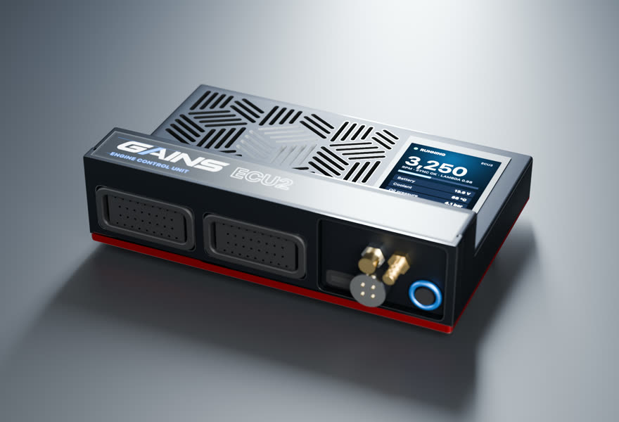
ECU2 for the JZ swap
Planned with the same rules as the configurator for this car's 6 cyl · port injection · cable throttle. The factory ECU is unplugged and replaced; nothing is written to it.
- Price TBA
ECU2Engine controller
6 cyl · port injection · cable throttle
Full sequential fuel and spark for this 6-cylinder on a cable throttle, with the wideband built in.
in designEst. availability: April 2027
Add PDM2 to switch and protect chassis loads (pumps, fans, lights, accessories). Add it in the configurator →
Track days? Add the Telemetry Dongle Pro for 25 Hz GPS lap timing; it plugs into the OBD-II port, and your phone is the dash. Plan it in the configurator →
What you get
- A screen on the ECUA 2.4-inch, 500-nit display in the lid, readable in a footwell.
- Faults in plain words"Coolant temp sensor open circuit.
- S3-style harnessesConnector A and C pin functions follow the published Nexus S3 wiring diagram.
- Powered CAN portA sealed 4-pin port on the insert carries 12 V and CAN for the PDM2 and GAINS displays: one cable per accessory.
- GAINS insideThe on-ECU adaptive layer, the app, logging and your limits.
How it wires in
- Haltech S3 plug-in harnessNone listed for this car
- Factory-connector → S3 adapter4 listed · from $840 USD listBF29105-S3
- Wire-inAlways possible
Pin-compatible per the published S3 pinout, not yet fit-tested. Every harness option for this car ↓
ECU2 is in design; specifications may change. All GAINS hardware is pre-release concept design; nothing is for sale yet and no application is validated on a vehicle. Harness fitment is from published pinouts and not yet fit-tested.
Swap guides
The 2JZ-GTE (non-VVT-i) family in other cars
How GAINS approaches the JZ swap
Our starting method for this engine, as foundations first: get it running and drivable, then learn fuel, then the hardware-specific strategies. It is a methodology outline, not a validated calibration.
- 1Base map and first startplanned
Start from displacement, injector data and the sensors fitted, then let the first-start learner settle cranking, idle and warm-up before any load work. The goal is a safe, running engine, not a finished calibration.
- 2Lambda targets and VE learningclosed loop on GAINS ECUs
Air-fuel targets come from your goal (street, track, economy). The ECU then learns its fuel table cell by cell from the onboard wideband inside a signed envelope, and you approve promoting what it learned into the base map.
- 3Boost controlgated
A closed-loop boost target by gear and goal, held inside the authority envelope, with knock protection active at boost. Raising boost authority is never automatic; it stays an expert or dyno decision.
- 4Drivability foundationsplanned
Pedal map, tip-in and decel fuel, idle control, cold start and warm-up enrichment: the tables tuners spend hours on after the main map. Each is a strategy in the knowledge engine with its own limits.
- 5Factory load sensingfactory reference
What the factory ECU measures load with: varies by year/market (low confidence); Forum consensus only: JDM 2JZ-GTE MAP (D-type); US/EU Supra Turbo uses an air-flow meter (aftermarket MAP-ECU sold to remove it) with MAP part 89421-20200 used for boost. No OEM doc read; Karman-vortex vs hot-wire on US car unconfirmed.
- 6Wideband sensorhardware
Add a wideband: the factory narrowband only tells rich from lean around stoichiometric, so it cannot close the loop at power or economy targets; fit a Bosch LSU 4.9 for the GAINS ECU's built-in controller
- 7Bottom end and head sealingfactory reference
Reported: Stock cast pistons are commonly reported as the first bottom-end limit; the oil pump drive is reported (MotoIQ) as the first part to suffer from torsional vibration at high rpm. (medium confidence) Limits depend on tune quality, fuel, rpm and condition and are not guaranteed.
Drivetrain
Chassis integration
- Factory ECMs output engine speed and read a vehicle speed signal (SP1)
- A standalone must provide the target chassis' tach signal format
Plan the target chassis interface early: tachometer drive, coolant gauge sender, fuel pump control, cooling fan control, A/C compressor request and any CAN or immobilizer requirements of the receiving car. Toyota donor engines have their own coolant sender and oil pressure switch threads, which may not match the host gauges.
Tuning notes
Export 2JZ-GTE injectors measure about 1.95 ohm and run with a solenoid resistor
Sourced5A 2JZ-GE converted to turbo keeps its higher compression, so it has less knock margin on pump fuel than a 2JZ-GTE; budget for E85 or conservative boost. On VVT-i 1JZ/2JZ engines, tune cam targets alongside fuel and ignition because VVT-i changes trapped mass and residual gas.
Popular swaps
Hardware checklist: engine mounts or adapter plates, sump and oil pickup orientation to clear the crossmember, gearbox and bellhousing, driveshaft, intercooler and charge piping, radiator and fans, exhaust routing and a fuel system sized for the target power with a return line if using the factory regulator.
GAINS on the JZ swap
ECU2
Designed so your phone is the laptop, keypad and dash
The GAINS app is designed to handle tuning, logging, gauges and switch inputs over Bluetooth, so the system needs no separate CAN keypad or display. Keypad, dash and logging views are planned; the iOS prototype runs on simulated data today.
Wideband, IMU and logging built in
An onboard Bosch LSU 4.9 wideband controller, a 6-axis IMU and onboard logging are designed into the ECU rather than sold as add-on modules.
Modular, so you buy what the engine needs
This engine runs on ECU2. PDM2 (power, body and gearbox) is optional and connects over ECU2's powered CAN port; the Telemetry Dongle Pro adds GPS lap timing from the OBD-II port.
Calibration that keeps learning
Instead of a fixed map that drifts as parts and conditions change, the ECU keeps adapting its fuel trims within limits you can see and approve in the app.
Adaptive tuning strategies
- VE learning closed loop on GAINS ECUs
Learns the fuel table from the onboard wideband as you drive, cell by cell, inside a signed authority envelope. Learned trims are promoted into the base map without a step in fuelling.
- Goal-based lambda targets closed loop on GAINS ECUs
Sets air-fuel targets from your goal (economy, response, power, safety margin) instead of a single fixed table.
- Knock protection protection
Listens for knock on a dedicated knock processor, pulls timing at once and restores it slowly. It only ever reduces advance.
- Warm-up, cranking, idle and transient fuel planned
The same learning approach applied to the tables tuners spend hours on after the main map is done.
- Spark advance and boost authority gated
Widening ignition advance or boost is never automatic. It stays an expert or dyno decision until validated knock detection exists for the engine family.
Already running another ECU? In advisor mode the same strategies read your logs and recommend exact table changes with the reasoning, which you apply in your ECU vendor's own software.
GAINS hardware is pre-release concept design. Simulated results only; nothing is validated on a vehicle yet.
Frequently asked
Can I use the factory ECU for a 2JZ swap?
Only if the donor ECU and harness are transplanted together and fed every input they expect; single-turbo conversions remove the sequential-turbo VSVs the factory ECU controls, so most swaps use a standalone.53
Do 2JZ-GTE injectors need a resistor on a standalone?
Export 2JZ-GTE injectors are low impedance (about 1.95 ohm) and use a solenoid resistor; keep it or use peak-and-hold drivers.5
Is the 1JZ or 2JZ better for a swap?
Both share the 86 mm bore; the 2JZ has a longer 86 mm stroke (3.0 L) versus 71.5 mm (2.5 L) for the 1JZ, giving more torque, while the 1JZ is lighter-revving. Choose on budget, availability and target power.17
Does a VVT-i JZ need special ECU support?
Yes. The ECU must read the intake cam position and drive the oil control valve to a target angle.7
Sources
Numbered as cited above. Hover or tap a citation chip to preview it.
- The Toyota JZ Engine Guide (Michael Knowling) · AutoSpeed (Web Publications Pty Ltd), archived copy · press · retrieved 2026-10-25
- 2002 Lexus IS 300 Specifications and Features · Lexus Canada (Toyota Canada Inc.) · oem · retrieved 2026-10-25
- Toyota Supra repair manual (1995 model), 2JZ-GTE engine troubleshooting: standard value of ECM terminals and ECM data (pages EG-510 to EG-513) · Toyota Motor Corporation (page images reproduced by toyota-supra.de) · service-manual · retrieved 2026-10-25
- Toyota launches all-new Supra (press release, 24 May 1993) · Toyota Motor Corporation · press · retrieved 2026-10-25
- 1997 Toyota Supra Repair Manual (RM502U), SFI (2JZ-GTE) section · Toyota Motor Corporation (copy hosted at personal.tcu.edu) · service-manual · retrieved 2026-10-25
- Toyota Supra A80 repair manual index (sections incl. W58 and V160 manual transmissions, A340E automatic, TRAC, ABS) · Toyota Motor Corporation (reproduced by toyota-supra.de) · service-manual · retrieved 2026-10-25
- The Development of a New Turbocharged Engine with an Intelligent Variable Valve Timing System and New High Efficiency Turbocharger (Toyota technical paper, 1996; web transcription) · Toyota Motor Corporation (hosted by 3sgte.com) · oem · retrieved 2026-10-25
Catalog data and evidence
- Catalog data, not yet expert-reviewed.
- No vehicle photos: illustrations only until licensed imagery is available.
- Catalog note: Single-turbo conversion assumed
- E-930 Haltech S3 adapter harness page (sourced, high confidence)
- E-932 Haltech S3 adapter harness page (sourced, high confidence)
- E-934 Boomslang identity (sourced, high confidence)
- E-935 Boomslang S3 catalog size (sourced, high confidence)
- E-900 Haltech Nexus S3 catalog (sourced, high confidence)
- E-941 S3 engine harness availability (inferred, medium confidence)
- E-1452 JZX100 ECU (reported, low confidence)
- E-1477 IS300 ECU (unverified-secondary, low confidence)
- E-1473 2JZ-GTE VVT-i ECU (unverified-secondary, low confidence)