

Bosch · Analog 0-5 V (ratiometric)
Bosch PST-F 2 280 bar DI rail pressure and temperature sensor
The Bosch PST-F 2 280 bar (0 261 545 115) measures absolute fuel pressure up to 280 bar and fuel temperature in gasoline direct-injection rails. Pressure output is 0.5-4.5 V ratiometric, 14.3 mV per bar plus 500 mV at 5 V; the NTC reads 10 kΩ at 25 °C. It is E26 and E85 compatible.2
Key specifications
Measures: Absolute DI rail pressure (0-280 bar) and fuel temperature. Output: Analog 0-5 V (ratiometric).
| Part number | Maker | Note |
|---|---|---|
| 0 261 545 115 | Bosch | 2 |
Pinout and connector
- Supply
- Ground / return
- Signal
- Shield
- Not used / not listed
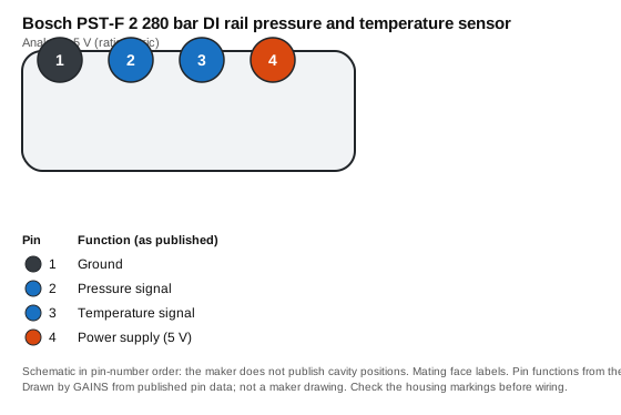
| Pin | Function (as published) | Typical ECU input | Wire note |
|---|---|---|---|
| 1 | Ground | Sensor ground | Return to sensor ground, not chassis |
| 2 | Pressure signal | Analog voltage input (pull-up off) | — |
| 3 | Temperature signal | Temperature input (pull-up on) | — |
| 4 | Power supply (5 V) | +5 V sensor reference | — |
Pin functions as published.2 The ECU-input and wire columns are our general guidance, not the maker's.
Connector: Hirschmann; mating part F02U.B00.596-012 Connector library
Terminals and seals: Not listed: the Bosch data sheet gives the mating housing only, not contact or seal part numbers.
Transfer function and calibration data
Ua = 0.5 V + 14.3 mV/bar × p (at Us = 5 V)
Points computed from Bosch's sensitivity and offset.
Show the 5 data points
| Absolute pressure (bar) | Output (V) |
|---|---|
| 0 | 0.5 |
| 70 | 1.501 |
| 140 | 2.502 |
| 210 | 3.503 |
| 280 | 4.504 |
Show the 20 data points
| Temperature (°C) | Resistance (Ω) |
|---|---|
| -40 | 243,241 |
| -30 | 135,753 |
| -20 | 78,716 |
| -10 | 47,258 |
| 0 | 29,287 |
| 10 | 18,684 |
| 20 | 12,240 |
| 25 | 10,000 |
| 30 | 8,218 |
| 40 | 5,642 |
| 50 | 3,955 |
| 60 | 2,826 |
| 70 | 2,055 |
| 80 | 1,519 |
| 90 | 1,141 |
| 100 | 868.4 |
| 110 | 669.9 |
| 120 | 523.2 |
| 130 | 413.3 |
| 140 | 330 |
How it's calibrated
ECU-neutral: enter these values in whichever ECU you use. Nominal values without the maker's tolerance band.
Transfer function
- 0.5–4.5 V → 0–28,000 kPa absolute (maker: Ua = 0.5 V + 14.3 mV/bar × p (at Us = 5 V))2Calculated from the maker's data
- NTC: 243,241 Ω at -40 °C falling to 330 Ω at 140 °C2
- Steinhart-Hart fit through -40 °C, 50 °C, 140 °C: A = 9.1832e-4, B = 2.5545e-4, C = 1.0628e-7 (largest error against the maker's table 0.02 °C).2Calculated from the maker's data
Worked conversion
- At 2.5 V the maker's transfer line gives 13,986 kPa absolute (2,028 psia).2Calculated from the maker's data
- At 25 °C the element is 10,000 Ω; with a 1 kΩ pull-up to 5 V the ECU sees 5 × 10,000 / (10,000 + 1,000) = 4.545 V.2Calculated from the maker's data
Pressure transfer at 5 V: output voltage to pressure (9 rows)Calculated from the maker's data
| Output (V) | Pressure (kPa absolute) | Pressure (psia) |
|---|---|---|
| 0.5 | 0 | 0 |
| 1 | 3496.5 | 507.12 |
| 1.5 | 6993 | 1014.25 |
| 2 | 10489.5 | 1521.37 |
| 2.5 | 13986 | 2028.5 |
| 3 | 17482.5 | 2535.62 |
| 3.5 | 20979 | 3042.75 |
| 4 | 24475.5 | 3549.87 |
| 4.5 | 27972 | 4057 |
Interpolated between the maker's published points; nominal values with no tolerance band.
Temperature sensor (NTC): resistance and ECU input voltage (20 rows)Calculated from the maker's data
| Temperature (°C) | Resistance (Ω) | V at 1 kΩ pull-up to 5 V | V at 2.2 kΩ pull-up to 5 V |
|---|---|---|---|
| -40 | 243241 | 4.98 | 4.955 |
| -30 | 135753 | 4.963 | 4.92 |
| -20 | 78716 | 4.937 | 4.864 |
| -10 | 47258 | 4.896 | 4.778 |
| 0 | 29287 | 4.835 | 4.651 |
| 10 | 18684 | 4.746 | 4.473 |
| 20 | 12240 | 4.622 | 4.238 |
| 25 | 10000 | 4.545 | 4.098 |
| 30 | 8218 | 4.458 | 3.944 |
| 40 | 5642 | 4.247 | 3.597 |
| 50 | 3955 | 3.991 | 3.213 |
| 60 | 2826 | 3.693 | 2.811 |
| 70 | 2055 | 3.363 | 2.415 |
| 80 | 1519 | 3.015 | 2.042 |
| 90 | 1141 | 2.665 | 1.708 |
| 100 | 868.4 | 2.324 | 1.415 |
| 110 | 669.9 | 2.006 | 1.167 |
| 120 | 523.2 | 1.717 | 0.961 |
| 130 | 413.3 | 1.462 | 0.791 |
| 140 | 330 | 1.241 | 0.652 |
Resistance from the maker's table. The maker does not state a pull-up; 1 kΩ and 2.2 kΩ are example values: use your ECU's actual pull-up.
Native support across ECUs
| ECU platform | Status | How to set it up | Source |
|---|---|---|---|
| GAINS ECU2Concept | To be confirmed | Rail pressure stays on the host ECU's own analog inputs (DI concept); the DI rail-pressure input is still an open item. | Medium7 |
| Haltech (Elite / Nexus) | Configurable (generic input) | Analog voltage input (AVI). Haltech's wiring diagram says inputs are user definable in software; enter the maker's transfer function. | 89 |
| Link (G4X) | Configurable (generic input) | Analogue voltage input (9 on the G4X FuryX). Link's public page does not describe how a custom calibration is entered. | Medium10 |
| MoTeC (M1) | Configurable (generic input) | Analogue voltage input (17 on the M150). MoTeC's sensor pages show a manual-calibration option in M1 Tune. | Medium1112 |
| ECUMaster (EMU Black) | Configurable (generic input) | One of 9 analog 0-5 V inputs. ECUMaster lists user-defined sensor characteristics for some functions. | Medium13 |
| AEM (Infinity) | Configurable (generic input) | Analog 0-5 V input (12-bit). AEM's spec sheet does not say how a custom calibration is entered. | Medium14 |
| MaxxECU | Configurable (generic input) | Extra 0-5 V input (6 on the RACE). The public page does not describe calibration entry. | Medium15 |
| Holley (Terminator X / EFI) | Configurable (generic input) | '5' analog input, set up as a custom sensor in Holley's software (per the wiring manual). | 16 |
Third-party rows come only from each vendor's public product pages, sensor lists and spec sheets, retrieved on the dates listed in Sources; we do not use ECU software, help files, base maps or calibration files, and reproduce no vendor calibration values. "Preset listed" means the vendor publicly names this sensor; "Configurable" means a matching generic input is listed. Check the vendor's current documentation before buying.
Trademarks belong to their owners. Names are used only to identify compatible products; no endorsement is implied.
CAD and drawings
- Data sheetPressure Sensor Combined PST-F 2 280 bar data sheet 70473483 (PDF)2Download from Bosch MotorsportNo login at last check; the maker may change this
- 3D CAD3D data (zip)56Download from Bosch MotorsportNo login at last check; the maker may change this
We link to the maker's own downloads and do not rehost their CAD or data sheets: the maker's terms do not grant redistribution. Registration may be needed on the maker's site.
Wiring and installation
Never open a direct-injection rail under pressure. Torque the sensor to Bosch's value and replace damaged sealing cones.Medium21
Bosch suggests a 4.6 kΩ pull-up for the temperature channel.2
Failure modes and checks
Likely cause Wrong offset entered (0.5 V = 0 bar)
Check Check the ECU uses 500 mV offset and 14.3 mV/bar.Medium2
Likely cause Damaged sealing cone or low torque
Check Replace and torque to 37.5 ± 2.5 N·m.Medium2
Test it with a multimeter
- Key on, engine off, port open to air: back-probe signal to sensor ground and expect about 0.51 V; the supply pin should read the ECU's 5 V reference.2Calculated from the maker's data
- Unplugged, measure resistance across the two element pins: about 10,000 Ω at 25 °C, falling as it warms (compare with the table).2Calculated from the maker's data
Frequently asked
What is the output of a 280 bar rail pressure sensor?
For the Bosch PST-F 2 280 bar: 0.5 V at 0 bar rising 14.3 mV per bar, so 200 bar reads about 3.36 V at 5 V supply.2
What is the pinout of the PST-F 2 280 bar?
Pin 1 ground, pin 2 pressure, pin 3 temperature, pin 4 5 V supply, on a Hirschmann connector.2
Related
Use it with GAINS
Bosch PST-F 2 280 bar DI rail pressure and temperature sensor on GAINS hardware
GAINS hardware is pre-release concept design; pin numbers can change before release and none of it has been tested on a vehicle yet.34
Concept Pre-release hardware. Pin assignments come from the current design documents and may change.
Sources
16 sources
- Automotive Handbook, 10th edition (2018) · Robert Bosch GmbH / Wiley · book · retrieved 2026-10-27
- Pressure Sensor Combined PST-F 2 280 bar data sheet 70473483 · Bosch Motorsport (Bosch Engineering GmbH) · vendor-doc · retrieved 2026-10-27
- internal GAINS internal: ECU2 concept and pin map v0.3 (hardware/mini-ecu/CONCEPT.md §3)
- internal GAINS internal: PDM2 input and output specification (hardware/mini-pdm/SPEC.md)
- PST F 2 280 product page · Bosch Motorsport · vendor-doc · retrieved 2026-10-27
- Bosch Motorsport legal notice · Bosch Motorsport (Robert Bosch GmbH) · vendor-doc · retrieved 2026-10-27
- internal GAINS internal: DI concept (hardware/mini-di/CONCEPT.md)
- Nexus R3 wiring diagram (HT-193000_WD) · Haltech · vendor-doc · retrieved 2026-10-27
- Nexus R3 VCU (HT-193000) product page · Haltech · vendor-doc · retrieved 2026-10-27
- G4X FuryX product page · Link Engine Management · vendor-doc · retrieved 2026-10-27
- M150 product page (M1 series) · MoTeC · vendor-doc · retrieved 2026-10-27
- TMAP Sensor product page · MoTeC · vendor-doc · retrieved 2026-10-27
- EMU Black product page · ECUMaster · vendor-doc · retrieved 2026-10-27
- Infinity Series 5 hardware specification · AEM Electronics · vendor-doc · retrieved 2026-10-27
- MaxxECU RACE product page · MaxxECU · vendor-doc · retrieved 2026-10-27
- HP / Dominator EFI wiring manual 199R10555 · Holley · vendor-doc · retrieved 2026-10-27
Not yet indexed: fewer than 3 FAQs.