

Engines for this swap: the GM LS (Gen III / IV) family
A swap has no factory engine. Pick your donor below; each links to its own specs, sensors and ECU.
Pick the engine variant in the planner
Platform background
This is a planning guide for putting a GM Gen III or Gen IV LS into a non-original chassis, from either a Chevrolet Performance crate engine or a junkyard donor. The main decisions are: the controller (factory-style GM PCM or Chevrolet Performance kit, versus a standalone), how the reluctor generation matches it, drive-by-wire versus cable, transmission control, fuel supply, and accessory drive and oil pan fit.
Factory ECU
- Chevrolet Performance Connect & Cruise and E-ROD packages include a pre-calibrated engine controller
- Contents vary by engine and typically include harness, MAF, O2 sensors and DBW pedal
E-ROD systems carry a California Air Resources Board (ARB) Executive Order for qualifying installations
Sourced · medium7Crate calibrations disable many production-vehicle features to avoid trouble codes
Sourced · medium3- Match PCM generation to the reluctor: Gen III P01/P59 for 24x, E38/E67 for 58x
- A conversion module lets a Gen III PCM run 58x
- Disable VATS
- Consider disabling rear O2/catalyst diagnostics, AFM and cam phasing
The cleanest swaps use a matched set of engine, harness and controller from the same generation. If you mix generations, choose the controller first and then fit whatever sensors, reluctor, cam gear and front cover it needs.
Factory ECU: harness cross-reference
From the factory ECU each listed harness plugs into. The factory ECU is unplugged, not modified. Check the label and part number on your own ECU before ordering.
- ECU family
- GM E38
- Applies to
- 2010-15 Camaro SS L99 6.2; automatic
- Not for
- LS3 manual (BF29996-S3); LSA/ZL1
E38 covers 2006-14 58X LS 6.2; separate TCM. L99 adds VVT/AFM vs LS3.
- ECU family
- GM E38
- Applies to
- 2010-15 Camaro LS3 (and LS7 Z/28); manual
- Not for
- L99 automatic
- ECU family
- GM E38
- Applies to
- 2006-13 Corvette LS2/LS3; automatic
2005 LS2 not covered by E38 range.
- ECU family
- GM E38
- Applies to
- 2006-13 Corvette LS2/LS3/LS7; manual
- ECU family
- GM E67 (LSA); LS9 ECM type unconfirmed
- Applies to
- 2009-15 CTS-V LSA, 2012-15 Camaro ZL1, Corvette ZR1 LS9; auto/manual
E67 sourced for LSA only; LS9 (ZR1) ECM type not confirmed - harness may cover two ECM types.
Factory ECU pinout
Each connector face drawn from the OEM service manual's pin data, with every terminal's function and wire colour where the manual prints it.
GM Gen III LS 24x PCM (2004 Corvette C5 pinout)
The C5 Corvette's Gen III LS1/LS6 powertrain control module (PCM) uses two 80-way connectors, C1 and C2, on a 24x crank trigger with a separate throttle actuator control module. This page transcribes GM's 2004 Corvette PCM connector tables: 160 cavities, each with wire colour, circuit number and function, plus the connector face layout.
2004 (pinout as documented); C5 1997-2004 · US · 2 connectors, 160 cavities · 160 terminals sourced
Looking into the harness plug's mating face (mirror of the ECU face).
How the OEM figure is oriented
GM's figure ("PCM Connector Terminal Identification C1/C2") is not labelled harness side or PCM side. It draws the 80-way connector face with two rows of two 20-cavity blocks either side of a centre bolt, latch housings along the top edge, cavity 1 bottom-left, 40 bottom-right, 41 top-left and 80 top-right; on the C2 figure 20/21 and 60/61 are printed either side of the bolt. GM connector end views normally show the harness connector mating face, which is how it is stored here; confirm against the numbers moulded on the connector before wiring.| Pin | Function | Type | Wire | Notes |
|---|---|---|---|---|
| 1 | Ground (circuit 451) | chassis/PCM ground | BLK/WHT | |
| 2 | 12-Volt Reference (circuit 1867) | 12 V sensor supply | LT GRN | GM prints only "12-Volt Reference". GM's CKP diagnostic (DTC P0335 family) describes the CKP sensor as 12-volt reference, low reference and signal circuits; the CMP sensor also has a 12-volt reference (C2 pin 39 is the other one in this table). Which reference feeds which sensor is not stated in the table, so confirm with the schematic before wiring. |
| 3 | Fuel Injector 3 Control (circuit 1746) | low-side injector driver | PNK/BLK | |
| 4 | Fuel Injector 2 Control (circuit 1745) | low-side injector driver | LT GRN/BLK | |
| 5 | Not used (per GM table) | Other / not used | — | |
| 6 | Not used (per GM table) | Other / not used | — | |
| 7 | 5-Volt Reference (circuit 596) | 5 V sensor supply | GRY | |
| 8 | Not used (per GM table) | Other / not used | — | |
| 9 | Not used (per GM table) | Other / not used | — | |
| 10 | Not used (per GM table) | Other / not used | — | |
| 11 | Knock Sensor 2 Signal (circuit 1876) | Sensor signal | LT BLU | |
| 12 | Crankshaft Position (CKP) Sensor Signal (circuit 1869) | Crank / cam | DK BLU/WHT | |
| 13 | Requested Torque Signal (circuit 463) | Comms / diag | ORN/BLK | Torque request link to the separate Throttle Actuator Control (TAC) module; the C5 is drive-by-wire. |
| 14 | Throttle Actuator Control Serial Data (circuit 800) | Comms / diag | TAN | Serial data link to the separate Throttle Actuator Control (TAC) module. |
| 15 | Throttle Actuator Control Serial Data (circuit 1061) | Comms / diag | ORN/BLK | Serial data link to the separate Throttle Actuator Control (TAC) module. |
| 16 | Not used (per GM table) | Other / not used | — | |
| 17 | Transmission Fluid Pressure Switch Signal B (circuit 1225) | Sensor signal | DK BLU | |
| 18 | Transmission Fluid Pressure Switch Signal C (circuit 1226) | Sensor signal | RED | |
| 19 | Ignition 1 Voltage (circuit 239) | ignition-switched 12 V input | PNK | |
| 20 | Battery Positive Voltage (circuit 340) | battery positive input | ORN | |
| 21 | Low Reference (circuit 1868) | sensor low reference (ground) | YEL/BLK | |
| 22 | Not used (per GM table) | Other / not used | — | |
| 23 | Low Reference (circuit 720) | sensor low reference (ground) | GRY | |
| 24 | Ground (circuit 451) | chassis/PCM ground | BLK/WHT | |
| 25 | HO2S Low Signal Bank 2 Sensor 2 (circuit 1671) | Sensor signal | TAN | |
| 26 | HO2S Low Signal Bank 2 Sensor 1 (circuit 1667) | Sensor signal | TAN | |
| 27 | Ground (circuit 451) | chassis/PCM ground | BLK/WHT | |
| 28 | HO2S Low Signal Bank 1 Sensor 2 (circuit 1669) | Sensor signal | TAN/WHT | |
| 29 | HO2S Low Signal Bank 1 Sensor 1 (circuit 1653) | Sensor signal | TAN/WHT | |
| 30 | Not used (per GM table) | Other / not used | — | |
| 31 | Not used (per GM table) | Other / not used | — | |
| 32 | Transmission Range Switch Signal A (circuit 771) | Sensor signal | BLK/WHT | |
| 33 | TCC Brake Switch Signal (circuit 420) | Sensor signal | PPL | |
| 34 | Transmission Range Switch Signal P (circuit 776) | Sensor signal | WHT | |
| 35 | CPP Switch Signal (circuit 48) | Sensor signal | GRY | |
| 36 | Fuel Injector 1 Control (circuit 1744) | low-side injector driver | BLK | |
| 37 | Fuel Injector 6 Control (circuit 846) | low-side injector driver | YEL/BLK | |
| 38 | Damping Lift/Dive Signal (circuit 1101) | Other / not used | PNK/WHT | Link to the C5 ride-control (damping) system. |
| 39 | Not used (per GM table) | Other / not used | — | |
| 40 | Ground (circuit 451) | chassis/PCM ground | BLK/WHT | |
| 41 | Not used (per GM table) | Other / not used | — | |
| 42 | Low Speed Cooling Fan Relay Control (circuit 335) | Outputs | DK GRN | |
| 43 | Fuel Injector 7 Control (circuit 877) | low-side injector driver | RED/BLK | |
| 44 | Fuel Injector 4 Control (circuit 844) | low-side injector driver | LT BLU/BLK | |
| 45 | 5-Volt Reference (circuit 474) | 5 V sensor supply | GRY | |
| 46 | 5-Volt Reference (circuit 598) | 5 V sensor supply | GRY | |
| 47 | Not used (per GM table) | Other / not used | — | |
| 48 | 5-Volt Reference (circuit 416) | 5 V sensor supply | GRY | |
| 49 | Not used (per GM table) | Other / not used | — | |
| 50 | Not used (per GM table) | Other / not used | — | |
| 51 | Knock Sensor 1 Signal (circuit 496) | Sensor signal | DK BLU | |
| 52 | Not used (per GM table) | Other / not used | — | |
| 53 | Low Reference (circuit 1057) | sensor low reference (ground) | ORN/BLK | |
| 54 | Low Reference (circuit 469) | sensor low reference (ground) | ORN/BLK | |
| 55 | Not used (per GM table) | Other / not used | — | |
| 56 | Not used (per GM table) | Other / not used | — | |
| 57 | Battery Positive Voltage (circuit 340) | battery positive input | ORN | |
| 58 | PCM Class 2 Serial Data (circuit 1049) | Comms / diag | DK GRN | |
| 59 | Not used (per GM table) | Other / not used | — | |
| 60 | Low Reference (circuit 407) | sensor low reference (ground) | BLK | |
| 61 | Low Reference (circuit 632) | sensor low reference (ground) | PNK/BLK | |
| 62 | Extended Travel Brake Switch Signal (circuit 847) | Sensor signal | GRY | |
| 63 | Low Reference (circuit 452) | sensor low reference (ground) | BLK | |
| 64 | Ground (circuit 451) | chassis/PCM ground | BLK/WHT | |
| 65 | HO2S High Signal Bank 2 Sensor 2 (circuit 1670) | Sensor signal | PPL | |
| 66 | HO2S High Signal Bank 2 Sensor 1 (circuit 1666) | Sensor signal | PPL | |
| 67 | Ground (circuit 451) | chassis/PCM ground | BLK/WHT | |
| 68 | HO2S High Signal Bank 1 Sensor 2 (circuit 1668) | Sensor signal | PPL/WHT | |
| 69 | HO2S High Signal Bank 1 Sensor 1 (circuit 1665) | Sensor signal | PPL/WHT | |
| 70 | Oil Level Switch Signal (circuit 1174) | Sensor signal | BRN | |
| 71 | Not used (per GM table) | Other / not used | — | |
| 72 | Transmission Range Switch Signal B (circuit 772) | Sensor signal | YEL | |
| 73 | Camshaft Position (CMP) Sensor Signal (circuit 633) | Crank / cam | BRN/WHT | |
| 74 | Engine Coolant Temperature (ECT) Sensor Signal (circuit 410) | Sensor signal | YEL | |
| 75 | Not used (per GM table) | Other / not used | — | |
| 76 | Fuel Injector 5 Control (circuit 845) | low-side injector driver | BLK/WHT | |
| 77 | Fuel Injector 8 Control (circuit 878) | low-side injector driver | DK BLU/WHT | |
| 78 | Not used (per GM table) | Other / not used | — | |
| 79 | Skip Shift Solenoid Control (manual) or 3-2 Shift Solenoid Valve Control (automatic) (circuits 587 / 687) | Outputs | GRY or WHT | GM's table lists two entries for this cavity: GRY circuit 587 Skip Shift Solenoid Control and WHT circuit 687 3-2 Shift Solenoid Valve Control. No option code is printed on this row; the skip-shift solenoid belongs to the manual gearbox and the 3-2 shift solenoid valve to the automatic, so only one is populated per car. Check the car's transmission before wiring. |
| 80 | Low Reference (circuit 718) | sensor low reference (ground) | BRN |
Our drawing from published pin data; not an OEM drawing. Layout from the OEM face view (medium confidence). Confirm against the factory manual for your exact year and market before cutting or pinning wires.
Looking into the harness plug's mating face (mirror of the ECU face).
How the OEM figure is oriented
GM's figure ("PCM Connector Terminal Identification C1/C2") is not labelled harness side or PCM side. It draws the 80-way connector face with two rows of two 20-cavity blocks either side of a centre bolt, latch housings along the top edge, cavity 1 bottom-left, 40 bottom-right, 41 top-left and 80 top-right; on the C2 figure 20/21 and 60/61 are printed either side of the bolt. GM connector end views normally show the harness connector mating face, which is how it is stored here; confirm against the numbers moulded on the connector before wiring.| Pin | Function | Type | Wire | Notes |
|---|---|---|---|---|
| 1 | Ground (circuit 451) | chassis/PCM ground | BLK/WHT | |
| 2 | TCC PWM Solenoid Valve Control (circuit 418) | Outputs | BRN | |
| 3 | Not used (per GM table) | Other / not used | — | |
| 4 | AIR Solenoid Control (circuit 421) | Outputs | PPL | |
| 5 | Delivered Torque Signal (circuit 464) | Comms / diag | TAN/BLK | Torque feedback from the separate Throttle Actuator Control (TAC) module. |
| 6 | PC Solenoid valve High Control (circuit 1228) | Outputs | RED/BLK | |
| 7 | Not used (per GM table) | Other / not used | — | |
| 8 | PC Solenoid Valve Low Control (circuit 1229) | Outputs | LT BLU/WHT | |
| 9 | Fuel Pump Relay Control (circuit 465) | Outputs | DK GRN/WHT | |
| 10 | Engine Speed Signal (circuit 121) | Comms / diag | WHT | |
| 11 | Not used (per GM table) | Other / not used | — | |
| 12 | Not used (per GM table) | Other / not used | — | |
| 13 | Not used (per GM table) | Other / not used | — | |
| 14 | A/C Refrigerant Pressure Sensor Signal (circuit 380) | Sensor signal | RED/BLK | |
| 15 | Generator Turn On Signal (circuit 225) | Outputs | RED | |
| 16 | Not used (per GM table) | Other / not used | — | |
| 17 | A/C Request Signal (C60 only) (circuit 762) | Sensor signal | DK GRN/WHT | Printed "C60 only" (an RPO option code in the GM table). |
| 18 | A/C Compressor Clutch Supply Voltage (circuit 59) | Sensor signal | DK GRN | |
| 19 | Not used (per GM table) | Other / not used | — | |
| 20 | Signal Low - Front (circuit 401) | Sensor signal | PPL | Printed exactly as "Signal Low - Front"; the GM table does not name the sensor on circuits 400/401. |
| 21 | Signal High - Front (circuit 400) | Sensor signal | YEL | Printed exactly as "Signal High - Front"; the GM table does not name the sensor on circuits 400/401. |
| 22 | Not used (per GM table) | Other / not used | — | |
| 23 | Not used (per GM table) | Other / not used | — | |
| 24 | Not used (per GM table) | Other / not used | — | |
| 25 | IAT Sensor Signal (circuit 472) | Sensor signal | TAN | |
| 26 | IC 1 Control (circuit 2121) | ignition control output to coil (IC) | PPL | |
| 27 | IC 7 Control (circuit 2127) | ignition control output to coil (IC) | RED | |
| 28 | IC 6 Control (circuit 2126) | ignition control output to coil (IC) | LT BLU/WHT | |
| 29 | IC 4 Control (circuit 2124) | ignition control output to coil (IC) | DK GRN/WHT | |
| 30 | Not used (per GM table) | Other / not used | — | |
| 31 | MAF Sensor Signal (circuit 492) | Sensor signal | YEL | |
| 32 | MAP Sensor Signal (circuit 432) | Sensor signal | LT GRN | |
| 33 | High Speed Cooling Fan Relay Control (circuit 473) | Outputs | DK BLU | |
| 34 | EVAP Canister Purge Solenoid Control (circuit 428) | Outputs | DK GRN/WHT | |
| 35 | Not used (per GM table) | Other / not used | — | |
| 36 | AIR Pump Relay Control (circuit 436) | Outputs | BRN | |
| 37 | Not used (per GM table) | Other / not used | — | |
| 38 | Not used (per GM table) | Other / not used | — | |
| 39 | 12-Volt Reference (circuit 631) | 12 V sensor supply | RED | |
| 40 | Ground (circuit 451) | chassis/PCM ground | BLK/WHT | |
| 41 | Not used (per GM table) | Other / not used | — | |
| 42 | TCC Solenoid Valve Control (circuit 422) | Outputs | TAN/BLK | |
| 43 | A/C Compressor Clutch Relay Control (circuit 459) | Outputs | DK GRN/WHT | |
| 44 | Reverse Lockout Solenoid Control (circuit 1652) | Outputs | LT GRN | |
| 45 | EVAP Canister Vent Solenoid Control (circuit 1310) | Outputs | WHT | |
| 46 | Malfunction Indicator Lamp (MIL) Control (circuit 419) | Outputs | BRN/WHT | |
| 47 | Skip Shift Indicator Control (MM6) or 2-3 Shift Solenoid Valve Control (M30) (circuits 375 / 1223) | Outputs | WHT or YEL/BLK | GM's table lists two entries: WHT circuit 375 Skip Shift Indicator Control (MM6, manual) and YEL/BLK circuit 1223 2-3 Shift Solenoid Valve Control (M30, automatic). |
| 48 | 1-2 Shift Solenoid Valve Control (circuit 1222) | Outputs | LT GRN | |
| 49 | Not used (per GM table) | Other / not used | — | |
| 50 | Vehicle Speed Signal (circuit 817) | Other / not used | DK GRN/WHT | |
| 51 | TFT Sensor Signal (circuit 1227) | Sensor signal | YEL/BLK | |
| 52 | HO2S Heater Low Control (circuit 2391) | HO2S heater low-side control | BRN | |
| 53 | HO2S Heater Low Control (circuit 3223) | HO2S heater low-side control | RED/WHT | |
| 54 | Fuel Level Sensor Signal (circuit 1936) | Sensor signal | DK BLU | |
| 55 | Not used (per GM table) | Other / not used | — | |
| 56 | Not used (per GM table) | Other / not used | — | |
| 57 | Low Reference (circuit 719) | sensor low reference (ground) | PPL | |
| 58 | Oil Pressure Sensor Signal (circuit 331) | Sensor signal | TAN/WHT | |
| 59 | Not used (per GM table) | Other / not used | — | |
| 60 | Low Reference (circuit 2129) | sensor low reference (ground) | BRN | |
| 61 | Low Reference (circuit 2130) | sensor low reference (ground) | BRN/WHT | |
| 62 | Transmission Range Switch Signal C (circuit 773) | Sensor signal | GRY | |
| 63 | Transmission Fluid Pressure Switch Signal A (circuit 1224) | Sensor signal | PNK | |
| 64 | Fuel Tank Pressure Sensor Signal (circuit 890) | Sensor signal | DK GRN | |
| 65 | Not used (per GM table) | Other / not used | — | |
| 66 | IC 8 Control (circuit 2128) | ignition control output to coil (IC) | PPL/WHT | |
| 67 | IC 2 Control (circuit 2122) | ignition control output to coil (IC) | RED/WHT | |
| 68 | IC 5 Control (circuit 2125) | ignition control output to coil (IC) | DK GRN | |
| 69 | IC 3 Control (circuit 2123) | ignition control output to coil (IC) | LT BLU | |
| 70 | Not used (per GM table) | Other / not used | — | |
| 71 | Not used (per GM table) | Other / not used | — | |
| 72 | HO2S Heater Low Control (circuit 3113) | HO2S heater low-side control | BLK/WHT | |
| 73 | Fuel Level Sensor Signal (Secondary) (circuit 1937) | Sensor signal | LT BLU | |
| 74 | HO2S Heater Low Control (circuit 3212) | HO2S heater low-side control | LT GRN | |
| 75 | Generator Field Duty Cycle Signal (circuit 23) | Sensor signal | GRY | |
| 76 | Not used (per GM table) | Other / not used | — | |
| 77 | Not used (per GM table) | Other / not used | — | |
| 78 | Not used (per GM table) | Other / not used | — | |
| 79 | Not used (per GM table) | Other / not used | — | |
| 80 | Low Reference (circuit 407) | sensor low reference (ground) | BLK |
Our drawing from published pin data; not an OEM drawing. Layout from the OEM face view (medium confidence). Confirm against the factory manual for your exact year and market before cutting or pinning wires.
Coverage, year splits and safety
Scope: every pin row is the 2004 model-year Corvette table (Engine Controls, 5.7L). Tables for 1997-2003 C5 cars were not checked for this file, so on those cars compare each wire colour and circuit number at the connector before cutting anything.
Corvette only. The 1998-2002 Camaro and Firebird LS1 (cable throttle, no TAC module) and the Gen III trucks also use 24x LS PCMs, but their GM connector tables were not available from an allowed source for this file and were not compared. Do not assume the Corvette pin functions carry over; the Camaro, Firebird, truck, Monaro and GTO catalog rows are deliberately not linked here.
The C5 is drive-by-wire: the PCM talks to a separate Throttle Actuator Control (TAC) module over C1 pins 13-15 and C2 pin 5. The TAC module connectors are not covered here. GM's table prints connector C1 with a blue TPA and C2 with a green TPA for this model year.
The common hardware names P01 and P59 (and the 24x / 58x split between Gen III and Gen IV) are enthusiast shorthand; they are not printed in the GM tables used here, and no PCM service part numbers were sourced, so none are listed.
Safety: disconnect the battery before unplugging the PCM, release the centre bolt rather than prying the connectors, and do not back-probe through the sealed connector rear with sharp probes; probe from the mating face with a proper terminal test adapter. Two cavities (C1 79 and C2 47) carry different circuits on manual and automatic cars.
Donor ECU pinouts still pending
No OEM pin table is in our library yet for these donor engines: 5.3 LM7 / L59 / LY5 (Gen III/IV truck), 6.0 LQ4 / LQ9 / LY6 / L96 (truck), LS2, LS3 / L99, L76 / L77 (6.0 Gen IV), LS7, LSA (supercharged), LS9 (supercharged). Generic swap page with no single factory connector. Use the donor vehicle's GM service manual PCM/ECM terminal tables, or the Chevrolet Performance controller kit instruction sheet for crate installs. Until then, wire from the harness maker's instructions or the factory service manual.
Plug-and-play harness
A swap has no single factory loom, so the harness follows the donor engine and loom you use. Each option below names its donor: pick the one that matches your engine and its loom, or use the wire-in harness for a loom you build yourself. Nothing is written to any factory ECU. Pin-compatible per the published S3 pinout, not yet fit-tested.
| Maker | Harness | Fits | Link | |
|---|---|---|---|---|
 | Auto 2010 - 2015 Chevrolet Camaro L99BF29995-S3 | 2010-15 Camaro SS L99 6.2; automatic | $1,445Lowest | Maker ↗ |
| Manual 2010 - 2015 Chevrolet Camaro LS3BF29996-S3 | 2010-15 Camaro LS3 (and LS7 Z/28); manual | $1,445Lowest | Maker ↗ |
| Auto 2008 - 2013 Chevrolet Corvette LS3BF29997-S3 | 2006-13 Corvette LS2/LS3; automatic | $1,445Lowest | Maker ↗ |
| Manual 2008 - 2013 Chevrolet Corvette LS3BF29998-S3 | 2006-13 Corvette LS2/LS3/LS7; manual | $1,445Lowest | Maker ↗ |
| Manual 2010 - 2015 Chevrolet Camaro LSABF29999-S3 | 2009-15 CTS-V LSA, 2012-15 Camaro ZL1, Corvette ZR1 LS9; auto/manual | $1,445Lowest | Maker ↗ |
| Wire-in | Universal flying lead or re-terminated factory harness | Any engine (terminate to ECU2's two Superseal 34 connectors) | Universal harness from $405 | Maker ↗ |
Boomslang plug-and-play harness for Haltech Nexus S3 - Auto 2010 - 2015 Chevrolet Camaro L99
For a donor engine and loom from: Auto 2010 - 2015 Chevrolet Camaro L99
- Plugs into
GM E38 ECM (2010-15 Camaro SS L99)
- ECU
- GM E38
- Confidence
- medium
E38 covers 2006-14 58X LS 6.2; separate TCM. L99 adds VVT/AFM vs LS3.
Sources: E-1454
- Fits
- 2010-15 Camaro SS L99 6.2; automatic
- Exclusions
- LS3 manual (BF29996-S3); LSA/ZL1
- SKU
- BF29995-S3
- Maker fitment
- Chevrolet Camaro L99 (Auto); selector years 2010-2015; SKU label: Auto 2010 - 2015 Chevrolet Camaro L99
- Maker notes
- separate SKUs exist for other Nexus models (-S2/-R3/-R5/-T1/-T2); L99 auto
Boomslang plug-and-play harness for Haltech Nexus S3 - Manual 2010 - 2015 Chevrolet Camaro LS3
For a donor engine and loom from: Manual 2010 - 2015 Chevrolet Camaro LS3
- Plugs into
- Fits
- 2010-15 Camaro LS3 (and LS7 Z/28); manual
- Exclusions
- L99 automatic
- SKU
- BF29996-S3
- Maker fitment
- Chevrolet Camaro LS3; Chevrolet Camaro LS7 (Manual); selector years 2010-2015; SKU label: Manual 2010 - 2015 Chevrolet Camaro LS3
- Maker notes
- separate SKUs exist for other Nexus models (-S2/-R3/-R5/-T1/-T2); LS3 manual
Boomslang plug-and-play harness for Haltech Nexus S3 - Auto 2008 - 2013 Chevrolet Corvette LS3
For a donor engine and loom from: Auto 2008 - 2013 Chevrolet Corvette LS3
- Plugs into
GM E38 ECM (2006-13 Corvette LS2/LS3)
- ECU
- GM E38
- Confidence
- medium
2005 LS2 not covered by E38 range.
Sources: E-1454
- Fits
- 2006-13 Corvette LS2/LS3; automatic
- SKU
- BF29997-S3
- Maker fitment
- Chevrolet Corvette LS2; Chevrolet Corvette LS3 (Auto); selector years 2006-2013; SKU label: Auto 2008 - 2013 Chevrolet Corvette LS3
- Maker notes
- separate SKUs exist for other Nexus models (-S2/-R3/-R5/-T1/-T2); LS2 auto 2006-07
Boomslang plug-and-play harness for Haltech Nexus S3 - Manual 2008 - 2013 Chevrolet Corvette LS3
For a donor engine and loom from: Manual 2008 - 2013 Chevrolet Corvette LS3
- Plugs into
- Fits
- 2006-13 Corvette LS2/LS3/LS7; manual
- SKU
- BF29998-S3
- Maker fitment
- Chevrolet Corvette LS2; Chevrolet Corvette LS3; Chevrolet Corvette LS7 (Manual); selector years 2006-2013; SKU label: Manual 2008 - 2013 Chevrolet Corvette LS3
- Maker notes
- separate SKUs exist for other Nexus models (-S2/-R3/-R5/-T1/-T2); LS2 manual 2006-07
Boomslang plug-and-play harness for Haltech Nexus S3 - Manual 2010 - 2015 Chevrolet Camaro LSA
For a donor engine and loom from: Manual 2010 - 2015 Chevrolet Camaro LSA
- Plugs into
GM E67 ECM (LSA: CTS-V / Camaro ZL1; also Corvette LS9)
- ECU
- GM E67 (LSA); LS9 ECM type unconfirmed
- Confidence
- low
E67 sourced for LSA only; LS9 (ZR1) ECM type not confirmed - harness may cover two ECM types.
Sources: E-1454
- Fits
- 2009-15 CTS-V LSA, 2012-15 Camaro ZL1, Corvette ZR1 LS9; auto/manual
- SKU
- BF29999-S3
- Maker fitment
- Cadillac CTS-V LSA; Chevrolet Camaro LSA; Chevrolet Corvette LS9 (Auto/Manual); selector years 2009-2015; SKU label: Manual 2010 - 2015 Chevrolet Camaro LSA
- Maker notes
- separate SKUs exist for other Nexus models (-S2/-R3/-R5/-T1/-T2); LSA manual
Haltech and Boomslang are trademarks of their respective owners. GAINS is not affiliated with or endorsed by them.
Your GAINS system for this car · pre-release
ECU2 for the LS swap crate / junkyard
Planned with the same rules as the configurator for this car's 8 cyl · port injection · cable or drive-by-wire. The factory ECU is unplugged and replaced; nothing is written to it.
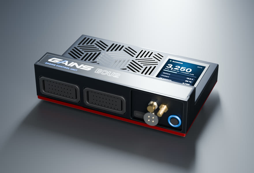
- Price TBA
ECU2Engine controller
8 cyl · port injection · cable or drive-by-wire
Full sequential fuel and spark for this 8-cylinder, and its electronic throttle, with the wideband built in.
in designEst. availability: April 2027
Add PDM2 to switch and protect chassis loads (pumps, fans, lights, accessories). Add it in the configurator →
Track days? Add the Telemetry Dongle Pro for 25 Hz GPS lap timing; it plugs into the OBD-II port, and your phone is the dash. Plan it in the configurator →
What you get
- A screen on the ECUA 2.4-inch, 500-nit display in the lid, readable in a footwell.
- Faults in plain words"Coolant temp sensor open circuit.
- Drive-by-wire built inFour half-bridges run up to two electronic throttles, with pedal and throttle sensors on the ECU's own inputs and a windowed watchdog that cuts the motors in hardware on a fault.
- S3-style harnessesConnector A and C pin functions follow the published Nexus S3 wiring diagram.
- Powered CAN portA sealed 4-pin port on the insert carries 12 V and CAN for the PDM2 and GAINS displays: one cable per accessory.
- GAINS insideThe on-ECU adaptive layer, the app, logging and your limits.
How it wires in
- Haltech S3 plug-in harnessNone listed for this car
- Factory-connector → S3 adapterNone listed for this car
- Wire-inYour route: universal wire-in harness
Pin-compatible per the published S3 pinout, not yet fit-tested. Every harness option for this car ↓
ECU2 is in design; specifications may change. All GAINS hardware is pre-release concept design; nothing is for sale yet and no application is validated on a vehicle. Harness fitment is from published pinouts and not yet fit-tested.
Swap guides
The LS3 / L99 family in other cars
How GAINS approaches the LS swap crate / junkyard
Our starting method for this engine, as foundations first: get it running and drivable, then learn fuel, then the hardware-specific strategies. It is a methodology outline, not a validated calibration.
- 1Base map and first startplanned
Start from displacement, injector data and the sensors fitted, then let the first-start learner settle cranking, idle and warm-up before any load work. The goal is a safe, running engine, not a finished calibration.
- 2Lambda targets and VE learningclosed loop on GAINS ECUs
Air-fuel targets come from your goal (street, track, economy). The ECU then learns its fuel table cell by cell from the onboard wideband inside a signed envelope, and you approve promoting what it learned into the base map.
- 3Cam phasing (VVT)gated
Begin with conservative overlap. Cam targets per load cell are then chosen with torque and knock in mind, keeping idle and cold overlap low for stability. Widening cam authority follows the same evidence-gated path as spark.
- 4Cylinder deactivationbuild choice
AFM / DFM / MDS / VCM is disabled in the build, with the lifter and valley-plate work the engine's guidance calls for.
- 5Drivability foundationsplanned
Pedal map, tip-in and decel fuel, idle control, cold start and warm-up enrichment: the tables tuners spend hours on after the main map. Each is a strategy in the knowledge engine with its own limits.
- 6Factory load sensingfactory reference
What the factory ECU measures load with: MAF+MAP (blended / torque model) (medium confidence)
- 7Wideband sensorhardware
factory O2 type not yet sourced; plan on a Bosch LSU 4.9 for the GAINS ECU's built-in controller
- 8Bottom end and head sealingfactory reference
Reported: Commonly reported that the powder-metal rods and hypereutectic pistons are the first limits under boost. (medium confidence) Limits depend on tune quality, fuel, rpm and condition and are not guaranteed.
Drivetrain
Chassis integration
- 24x engines run cable or DBW on GM electronics
- 58x engines only DBW with OEM controls
Plan the gauge signals early. Factory controllers output tach and vehicle speed signals, and newer ones broadcast coolant temperature and more over the network. Older chassis gauges may need converters or a new cluster.
Tuning notes
With a factory controller, calibrate for the actual intake, exhaust and MAF housing in the new chassis. MAF readings are sensitive to inlet ducting. Many swaps run speed density by disabling the MAF in the calibration.
Popular swaps
GAINS on the LS swap crate / junkyard
ECU2
Designed so your phone is the laptop, keypad and dash
The GAINS app is designed to handle tuning, logging, gauges and switch inputs over Bluetooth, so the system needs no separate CAN keypad or display. Keypad, dash and logging views are planned; the iOS prototype runs on simulated data today.
Wideband, IMU and logging built in
An onboard Bosch LSU 4.9 wideband controller, a 6-axis IMU and onboard logging are designed into the ECU rather than sold as add-on modules.
Modular, so you buy what the engine needs
This engine runs on ECU2. PDM2 (power, body and gearbox) is optional and connects over ECU2's powered CAN port; the Telemetry Dongle Pro adds GPS lap timing from the OBD-II port.
Calibration that keeps learning
Instead of a fixed map that drifts as parts and conditions change, the ECU keeps adapting its fuel trims within limits you can see and approve in the app.
Adaptive tuning strategies
- VE learning closed loop on GAINS ECUs
Learns the fuel table from the onboard wideband as you drive, cell by cell, inside a signed authority envelope. Learned trims are promoted into the base map without a step in fuelling.
- Goal-based lambda targets closed loop on GAINS ECUs
Sets air-fuel targets from your goal (economy, response, power, safety margin) instead of a single fixed table.
- Knock protection protection
Listens for knock on a dedicated knock processor, pulls timing at once and restores it slowly. It only ever reduces advance.
- Warm-up, cranking, idle and transient fuel planned
The same learning approach applied to the tables tuners spend hours on after the main map is done.
- Spark advance and boost authority gated
Widening ignition advance or boost is never automatic. It stays an expert or dyno decision until validated knock detection exists for the engine family.
Already running another ECU? In advisor mode the same strategies read your logs and recommend exact table changes with the reasoning, which you apply in your ECU vendor's own software.
GAINS hardware is pre-release concept design. Simulated results only; nothing is validated on a vehicle yet.
Frequently asked
What ECU do I need for an LS swap?
Match the engine generation. A 24x Gen III engine uses a P01/P59 PCM, and a 58x Gen IV engine uses an E38/E67 (or a Gen III PCM with a conversion module). Chevrolet Performance kits supply a pre-calibrated controller for crate engines.627
Do I need to turn off VATS for an LS swap?
Effectively yes. Factory PCMs expect the original vehicle's anti-theft signal, so swap calibrations disable it.1
What fuel pressure does an LS swap need?
About 58 psi, the OE rating for LS injectors, from a returnless system or a regulated return system.51
Can I use a cable throttle on an LS swap?
On 24x Gen III engines, yes, with a cable-throttle calibration. 58x Gen IV engines run only drive-by-wire with OEM controllers.6
Does an E-ROD LS3 kit have a California Air Resources Board Executive Order?
E-ROD packages carry a California Air Resources Board (ARB) Executive Order for qualifying vehicles, provided they are installed as specified.7
Sources
Numbered as cited above. Hover or tap a citation chip to preview it.
- LS Engine Controllers, Making Your LS-Power Change A Controlled Swap · Chevy Hardcore · press · retrieved 2026-10-25
- Dialing In LS Sensors For Various Generations With Michigan Motorsports · EngineLabs · press · retrieved 2026-10-25
- Chevrolet Performance LS3 E-ROD Connect & Cruise with 6L80-E (19421057K2) · JEGS · vendor-doc · retrieved 2026-10-25
- GM LS Engine RPO Codes Explained: LM7, L59, LQ4, LQ9 and L33 · JEGS · vendor-doc · retrieved 2026-10-25
- FIC 540cc LS3/LS7/LSA/L76/L92/L99 fuel injector set (rated at OE 58 psi) · Katech · vendor-doc · retrieved 2026-10-25
- 24x vs 58x Reluctor Differences for LS and LT · PSI Conversion · vendor-doc · retrieved 2026-10-25
- Chevrolet Performance Connect & Cruise Kits · Summit/SDPC (Scoggin Dickey Parts Center) · vendor-doc · retrieved 2026-10-25
- LS Swap How-To Guide · Speedway Motors · vendor-doc · retrieved 2026-10-25
- Tech: LS engine core options · Street Machine · press · retrieved 2026-10-25
Catalog data and evidence
- Catalog data, not yet expert-reviewed.
- No vehicle photos: illustrations only until licensed imagery is available.
- Catalog note: Pick the engine variant in the planner
- E-934 Boomslang identity (sourced, high confidence)
- E-935 Boomslang S3 catalog size (sourced, high confidence)
- E-900 Haltech Nexus S3 catalog (sourced, high confidence)
- E-941 S3 engine harness availability (inferred, medium confidence)
- E-1454 GM E38/E67 (supported, medium confidence)