


Engine: 2JZ-GE (NA, VVT-i 1998+)
Part of the Toyota JZ family. Throttle type varies by model/year
Modeled power and torque
Modelled estimate, not a dyno result.
Modeled estimate, not a dyno measurement. Real results vary with fuel, weather, dyno type and build.
Stock is anchored to the factory rating (222 hp at 6000 rpm, 209.8 lb-ft at 4800 rpm); the curve shape between peaks is modeled. Intake + exhaust + tune (pump fuel): Typical NA gains come mostly above mid-rpm.
2JZ-GE (NA, VVT-i 1998+) data
- Load sensing
- mixed by year/market
- O2 sensor
- Not yet sourced
- Closed loop
- Not yet sourced
- Block
- cast iron (skeleton structure, curved walls)
- Rods / pistons
- hot-forged, knock-pinned caps, plastic-region bolts; VVT-i: high-strength vanadium steel · aluminium, resin-coated skirts; oil jet sprays each piston underside
- Reported limit
- Not yet sourced
- Factory
- Denso top-feed · 315 cc/min
- Impedance
- high (saturated)
- Direct-fit upgrades
- 4 maker-listed
- Knock
- Toyota 89615-22040 | Toyota 89615-22030
- MAP / MAF
- not applicable: MAF-metered
- O2 (upstream)
- Toyota 89465-14120 | Toyota 89465-19605 | Toyota 89465-19625 | Toyota 89465-14140 (California)
Platform background
The Lexus IS300 (Toyota Altezza family) uses the 2JZ-GE VVT-i at 10.5:1 compression with ETCS-i electronic throttle (drive-by-wire), ACIS variable intake and twin knock sensors. Transmissions are a 5-speed automatic (ECT-i with E-shift) or a 5-speed manual on the sedan, with TRAC standard, VSC optional and an optional Torsen limited-slip differential. An encoded immobilizer is part of the factory theft-deterrent system.
Factory ECU
Computer-controlled sequential multi-port injection and ignition with twin knock sensors
Sourced1Because the IS300 is drive-by-wire, a replacement ECU must either control the electronic throttle with redundant pedal and throttle position sensing, or the car must be converted to a cable throttle. The immobilizer must also be satisfied or removed from the start authorisation path, which is a security-relevant change that should be done only with the owner's authority.
Factory ECU: harness cross-reference
From the factory ECU each listed harness plugs into. The factory ECU is unplugged, not modified. Check the label and part number on your own ECU before ordering.
- ECU family
- Toyota 2JZ-GE VVT-i
- Applies to
- 1998-2001 Aristo, GS300, IS300, SC300, Supra NA; auto/manual
One SKU across several chassis; ECM codes not verified.
- ECU family
- Toyota 2JZ-GE VVT-i
- Applies to
- 2002-05 GS300/IS300; 89661-53450 = 2005 IS300 manual example
Listing only; immobiliser-matched.
Factory ECU pinout
Each connector face drawn from the OEM service manual's pin data, with every terminal's function and wire colour where the manual prints it.
Lexus IS300 2JZ-GE VVT-i ECM (2001-2005, US)
The 2001-05 Lexus IS300 (2JZ-GE VVT-i, drive-by-wire) uses one ECM that also runs the A/T. Toyota changed it after 2001: the 2001 ECM has six plugs, E2 to E7 (148 cavities), and the 2002 ECM has five denser plugs, E3 to E7 (167 cavities), with different terminal numbers. Both are listed here from the Lexus repair manuals and wiring diagrams.
2001-2005 · USA (as documented in the US repair manuals); other markets not verified · 11 connectors, 315 cavities · 227 terminals sourced
Looking into the ECU's connector. The harness plug seen from its wire side has the same layout.
How the OEM figure is oriented
Terminals of ECM figure (RM779U DI-20, art A01888) as printed: the ECM drawn with its six connectors in a row, E7 E6 E5 E4 E3 E2 left to right, latch on top, each connector enlarged below with terminal numbers. Terminal 1 is at the top right of each connector and numbers run right to left. Toyota does not label the face, but the figure depicts the connector bank on the ECM, so it is recorded as ecu-side; confirm against the part before cutting a harness.| Pin | Function | Type | Wire | Notes |
|---|---|---|---|---|
| E2-9 | EOM (OEM symbol; W-B wire joined to the EC ground on the EWD) | ground | W-B | From the EWD only (not in the Terminals of ECM voltage table). (medium confidence) |
| E2-10 | Unlock warning switch input (KSW) | switch input | B-Y | From the EWD only (not in the Terminals of ECM voltage table). |
| E2-13 | VSV, pressure switching valve (TBP) | low-side solenoid driver | P | Listed in both the Terminals of ECM table and the EWD. |
| E2-20 | Security indicator light, via combination meter (IMLD) | lamp driver | L-B | From the EWD only (not in the Terminals of ECM voltage table). |
| E2-21 | Transponder key amplifier, TXCT line (TXCT) | serial | P | From the EWD only (not in the Terminals of ECM voltage table). The RM779U Terminals of ECM table prints the CCV return as "E01 (E2-21)"; the EWD shows E2-21 as TXCT and E01 on E7-21, so that table entry is a misprint. |
| E2-22 | Transponder key amplifier, RXCK line (RXCK) | serial | V | From the EWD only (not in the Terminals of ECM voltage table). |
| E2-23 | Transponder key amplifier, CODE line (CODE) | serial | G | From the EWD only (not in the Terminals of ECM voltage table). |
| E2-24 | Heated oxygen sensor signal (OXR2) | O2 sensor signal | W | Listed in both the Terminals of ECM table and the EWD. |
| E2-25 | Heated oxygen sensor heater control (HTR2) | low-side heater driver | R-W | Listed in both the Terminals of ECM table and the EWD. |
| E2-26 | Heated oxygen sensor heater control (HTL2) | low-side heater driver | G-B | Listed in both the Terminals of ECM table and the EWD. |
Our drawing from published pin data; not an OEM drawing. Layout from the OEM face view (medium confidence). Confirm against the factory manual for your exact year and market before cutting or pinning wires.
Looking into the ECU's connector. The harness plug seen from its wire side has the same layout.
How the OEM figure is oriented
Terminals of ECM figure (RM779U DI-20, art A01888) as printed: the ECM drawn with its six connectors in a row, E7 E6 E5 E4 E3 E2 left to right, latch on top, each connector enlarged below with terminal numbers. Terminal 1 is at the top right of each connector and numbers run right to left. Toyota does not label the face, but the figure depicts the connector bank on the ECM, so it is recorded as ecu-side; confirm against the part before cutting a harness.| Pin | Function | Type | Wire | Notes |
|---|---|---|---|---|
| E3-1 | Battery backup supply (BATT) | 12 V constant | B-Y | Listed in both the Terminals of ECM table and the EWD. |
| E3-4 | Fuel pump relay control, fuel pump resistor bypass (FPR) | relay driver | G-R | Listed in both the Terminals of ECM table and the EWD. |
| E3-5 | Circuit opening relay control (FC) | relay driver | G-Y | Listed in both the Terminals of ECM table and the EWD. |
| E3-6 | Check engine (MIL) warning lamp (W) | lamp driver | R-L | Listed in both the Terminals of ECM table and the EWD. |
| E3-7 | Throttle control motor power supply (+BM) | 12 V constant | L-W | Listed in both the Terminals of ECM table and the EWD. |
| E3-8 | Main supply from EFI relay (+B2) | 12 V switched | B-R | Listed in both the Terminals of ECM table and the EWD. |
| E3-9 | Ignition switch signal (IGSW) | 12 V input (IG ON) | B-O | Listed in both the Terminals of ECM table and the EWD. |
| E3-10 | EFI main relay control (MREL) | relay driver | B-O | Listed in both the Terminals of ECM table and the EWD. |
| E3-11 | Diagnostic serial line to DLC3 (SIL) | serial | W | Listed in both the Terminals of ECM table and the EWD. |
| E3-13 | Traction control link from ABS and traction ECU (TRC+) | Comms / diag | R-Y | From the EWD only (not in the Terminals of ECM voltage table). |
| E3-14 | Engine data link to ABS and traction ECU (ENG+) | Comms / diag | L-B | From the EWD only (not in the Terminals of ECM voltage table). |
| E3-15 | Engine speed output to ABS and traction ECU (NEO) | pulse output | G | From the EWD only (not in the Terminals of ECM voltage table). |
| E3-16 | Main supply from EFI relay (+B) | 12 V switched | B-R | Listed in both the Terminals of ECM table and the EWD. |
| E3-20 | Traction control link from ABS and traction ECU (TRC-) | Comms / diag | W-G | From the EWD only (not in the Terminals of ECM voltage table). |
| E3-21 | Engine data link to ABS and traction ECU (ENG-) | Comms / diag | P | From the EWD only (not in the Terminals of ECM voltage table). |
| E3-22 | ECM case / body ground (EC) | ground | W-B | From the EWD only (not in the Terminals of ECM voltage table). |
Our drawing from published pin data; not an OEM drawing. Layout from the OEM face view (medium confidence). Confirm against the factory manual for your exact year and market before cutting or pinning wires.
Looking into the ECU's connector. The harness plug seen from its wire side has the same layout.
How the OEM figure is oriented
Terminals of ECM figure (RM779U DI-20, art A01888) as printed: the ECM drawn with its six connectors in a row, E7 E6 E5 E4 E3 E2 left to right, latch on top, each connector enlarged below with terminal numbers. Terminal 1 is at the top right of each connector and numbers run right to left. Toyota does not label the face, but the figure depicts the connector bank on the ECM, so it is recorded as ecu-side; confirm against the part before cutting a harness.| Pin | Function | Type | Wire | Notes |
|---|---|---|---|---|
| E4-2 | Starter signal (STA) | 12 V input | B | Listed in both the Terminals of ECM table and the EWD. |
| E4-5 | Diagnostic TC terminal, DLC (TC) | 12 V input | R-W | Listed in both the Terminals of ECM table and the EWD. |
| E4-6 | Stop light switch input (STP) | 12 V input | G-W | Listed in both the Terminals of ECM table and the EWD. |
| E4-7 | Park/neutral position switch, 4 range input (4) | switch input | — | From the EWD only (not in the Terminals of ECM voltage table). Wire colour not printed next to this terminal on the EWD page. |
| E4-8 | Heated oxygen sensor signal (OXL2) | O2 sensor signal | W | Listed in both the Terminals of ECM table and the EWD. |
| E4-9 | FAN (EWD: from fan No. 1 / No. 2 relay and A/C diode) | Other / not used | L-B | From the EWD only (not in the Terminals of ECM voltage table). (medium confidence) |
| E4-10 | TAM (A/C system line on the EWD; OEM symbol only) | Other / not used | LG-R | From the EWD only (not in the Terminals of ECM voltage table). (medium confidence) |
| E4-11 | Stop light switch line for cruise control (ST1-) | switch input | B-L | From the EWD only (not in the Terminals of ECM voltage table). (medium confidence) |
| E4-13 | A/C compressor magnetic clutch relay control (ACMG) | relay driver | L-W | Listed in both the Terminals of ECM table and the EWD. |
| E4-14 | A/T shift main switch, down-shift (SFTD) | switch input | GR-R | From the EWD only (not in the Terminals of ECM voltage table). |
| E4-16 | Park/neutral position switch, R range input (R) | switch input | R-B | From the EWD only (not in the Terminals of ECM voltage table). |
| E4-17 | Park/neutral position switch, D range input (D) | switch input | GR-B | From the EWD only (not in the Terminals of ECM voltage table). |
| E4-18 | Vapor pressure sensor (PTNK) | 0-5 V analog | P-G | Listed in both the Terminals of ECM table and the EWD. |
| E4-21 | PRE (A/C pressure switch line on the EWD) | switch input | L-Y | From the EWD only (not in the Terminals of ECM voltage table). (medium confidence) |
| E4-23 | Cruise control main switch input (CCS) | resistor-ladder switch input | L-R | From the EWD only (not in the Terminals of ECM voltage table). |
| E4-25 | WFSE (OEM symbol; runs to junction IA1, function not stated on the EWD page) | Other / not used | LG | From the EWD only (not in the Terminals of ECM voltage table). (medium confidence) |
| E4-26 | Park/neutral position switch, P range input (P) | switch input | G | From the EWD only (not in the Terminals of ECM voltage table). |
| E4-27 | Body multiplex communication (MPX2) | multiplex | O | From the EWD only (not in the Terminals of ECM voltage table). |
| E4-28 | Body multiplex communication (MPX1) | multiplex | L | From the EWD only (not in the Terminals of ECM voltage table). |
Our drawing from published pin data; not an OEM drawing. Layout from the OEM face view (medium confidence). Confirm against the factory manual for your exact year and market before cutting or pinning wires.
Looking into the ECU's connector. The harness plug seen from its wire side has the same layout.
How the OEM figure is oriented
Terminals of ECM figure (RM779U DI-20, art A01888) as printed: the ECM drawn with its six connectors in a row, E7 E6 E5 E4 E3 E2 left to right, latch on top, each connector enlarged below with terminal numbers. Terminal 1 is at the top right of each connector and numbers run right to left. Toyota does not label the face, but the figure depicts the connector bank on the ECM, so it is recorded as ecu-side; confirm against the part before cutting a harness.| Pin | Function | Type | Wire | Notes |
|---|---|---|---|---|
| E5-1 | A/T shift solenoid S1 (S1) | solenoid driver | Y | From the EWD only (not in the Terminals of ECM voltage table). |
| E5-2 | A/T shift solenoid S2 (S2) | solenoid driver | G-Y | From the EWD only (not in the Terminals of ECM voltage table). |
| E5-3 | A/T shift solenoid S3 (S3) | solenoid driver | W-L | From the EWD only (not in the Terminals of ECM voltage table). |
| E5-4 | Direct clutch speed sensor + (NCO+) | VR + | R | From the EWD only (not in the Terminals of ECM voltage table). |
| E5-5 | Vehicle speed sensor (A/T output shaft) + (SP2+) | VR + | L-Y | Listed in both the Terminals of ECM table and the EWD. |
| E5-6 | A/T shift solenoid S4 (S4) | solenoid driver | W-G | From the EWD only (not in the Terminals of ECM voltage table). |
| E5-7 | A/T linear solenoid SLU + (SLU+) | linear solenoid driver | G-W | From the EWD only (not in the Terminals of ECM voltage table). |
| E5-8 | A/T linear solenoid SLN + (SLN+) | linear solenoid driver | Y-R | From the EWD only (not in the Terminals of ECM voltage table). |
| E5-9 | A/T linear solenoid SLT + (SLT+) | linear solenoid driver | B-Y | From the EWD only (not in the Terminals of ECM voltage table). |
| E5-10 | Direct clutch speed sensor - (NCO-) | VR - | G | From the EWD only (not in the Terminals of ECM voltage table). |
| E5-11 | Vehicle speed sensor (A/T output shaft) - (SP2-) | VR - | R-L | Listed in both the Terminals of ECM table and the EWD. |
| E5-12 | VSV, canister closed valve (CCV) | low-side solenoid driver | Y-G | Listed in both the Terminals of ECM table and the EWD. |
| E5-13 | A/T linear solenoid SLU - (SLU-) | linear solenoid return | L-R | From the EWD only (not in the Terminals of ECM voltage table). |
| E5-14 | A/T linear solenoid SLN - (SLN-) | linear solenoid return | R-W | From the EWD only (not in the Terminals of ECM voltage table). |
| E5-15 | A/T linear solenoid SLT - (SLT-) | linear solenoid return | R-B | From the EWD only (not in the Terminals of ECM voltage table). |
| E5-17 | A/T fluid temperature sensor (OIL) | 0-5 V analog | GR | From the EWD only (not in the Terminals of ECM voltage table). |
Our drawing from published pin data; not an OEM drawing. Layout from the OEM face view (medium confidence). Confirm against the factory manual for your exact year and market before cutting or pinning wires.
Looking into the ECU's connector. The harness plug seen from its wire side has the same layout.
How the OEM figure is oriented
Terminals of ECM figure (RM779U DI-20, art A01888) as printed: the ECM drawn with its six connectors in a row, E7 E6 E5 E4 E3 E2 left to right, latch on top, each connector enlarged below with terminal numbers. Terminal 1 is at the top right of each connector and numbers run right to left. Toyota does not label the face, but the figure depicts the connector bank on the ECM, so it is recorded as ecu-side; confirm against the part before cutting a harness.| Pin | Function | Type | Wire | Notes |
|---|---|---|---|---|
| E6-1 | ECM ground (E03) | ground | BR | From the EWD only (not in the Terminals of ECM voltage table). |
| E6-2 | Sensor 5 V supply (VC) | 5 V reference | L-Y | Listed in both the Terminals of ECM table and the EWD. |
| E6-3 | Heated oxygen sensor heater control (HTR) | low-side heater driver | P | Listed in both the Terminals of ECM table and the EWD. |
| E6-4 | Heated oxygen sensor heater control (HTL) | low-side heater driver | LG | Listed in both the Terminals of ECM table and the EWD. |
| E6-5 | Injector No. 1 (#10) | low-side injector driver | R | Listed in both the Terminals of ECM table and the EWD. |
| E6-6 | Injector No. 2 (#20) | low-side injector driver | L | Listed in both the Terminals of ECM table and the EWD. |
| E6-7 | VSV for EVAP purge (PRG) | low-side solenoid driver | W-G | Listed in both the Terminals of ECM table and the EWD. |
| E6-8 | Engine oil pressure switch input (MOPS) | switch input | GR | From the EWD only (not in the Terminals of ECM voltage table). |
| E6-9 | Power steering oil pressure sensor (PSP) | 0-5 V analog | V | From the EWD only (not in the Terminals of ECM voltage table). |
| E6-10 | Mass air flow meter signal (VG) | 0-5 V analog | G-B | Listed in both the Terminals of ECM table and the EWD. |
| E6-11 | Heated oxygen sensor signal (OXR1) | O2 sensor signal | B | Listed in both the Terminals of ECM table and the EWD. |
| E6-12 | Heated oxygen sensor signal (OXL1) | O2 sensor signal | W | Listed in both the Terminals of ECM table and the EWD. |
| E6-13 | Park/neutral position switch, N range input (N) | switch input | G-R | From the EWD only (not in the Terminals of ECM voltage table). |
| E6-14 | Engine coolant temperature sensor (THW) | 0-5 V analog | R | Listed in both the Terminals of ECM table and the EWD. |
| E6-15 | Accelerator pedal position sensor, main (VPA) | 0-5 V analog | P-L | Listed in both the Terminals of ECM table and the EWD. |
| E6-16 | Accelerator pedal position sensor, sub (VPA2) | 0-5 V analog | L-W | Listed in both the Terminals of ECM table and the EWD. |
| E6-17 | ECM signal ground (E1) | signal ground | BR | Listed in both the Terminals of ECM table and the EWD. |
| E6-18 | Sensor ground (E2) | sensor ground | BR | Listed in both the Terminals of ECM table and the EWD. The RM779U Terminals of ECM table prints this sensor-ground terminal as "E7 (E6-18)"; the EWD labels it E2. |
| E6-19 | Mass air flow meter ground (EVG) | sensor ground | L | Listed in both the Terminals of ECM table and the EWD. |
| E6-20 | Park/neutral position switch, 3 range input (3) | switch input | G-W | From the EWD only (not in the Terminals of ECM voltage table). |
| E6-21 | Park/neutral position switch, 2 range input (2) | switch input | R-B | From the EWD only (not in the Terminals of ECM voltage table). |
| E6-22 | Intake air temperature sensor (THA) | 0-5 V analog | L-B | Listed in both the Terminals of ECM table and the EWD. |
| E6-23 | Throttle position sensor, main (VTA) | 0-5 V analog | W-R | Listed in both the Terminals of ECM table and the EWD. |
| E6-24 | Throttle position sensor, sub (VTA2) | 0-5 V analog | G-Y | Listed in both the Terminals of ECM table and the EWD. |
Our drawing from published pin data; not an OEM drawing. Layout from the OEM face view (medium confidence). Confirm against the factory manual for your exact year and market before cutting or pinning wires.
Looking into the ECU's connector. The harness plug seen from its wire side has the same layout.
How the OEM figure is oriented
Terminals of ECM figure (RM779U DI-20, art A01888) as printed: the ECM drawn with its six connectors in a row, E7 E6 E5 E4 E3 E2 left to right, latch on top, each connector enlarged below with terminal numbers. Terminal 1 is at the top right of each connector and numbers run right to left. Toyota does not label the face, but the figure depicts the connector bank on the ECM, so it is recorded as ecu-side; confirm against the part before cutting a harness.| Pin | Function | Type | Wire | Notes |
|---|---|---|---|---|
| E7-1 | Injector No. 3 (#30) | low-side injector driver | G | Listed in both the Terminals of ECM table and the EWD. |
| E7-2 | Injector No. 4 (#40) | low-side injector driver | R-W | Listed in both the Terminals of ECM table and the EWD. |
| E7-3 | Injector No. 5 (#50) | low-side injector driver | L-R | Listed in both the Terminals of ECM table and the EWD. |
| E7-4 | Injector No. 6 (#60) | low-side injector driver | B-W | Listed in both the Terminals of ECM table and the EWD. |
| E7-5 | VSV for ACIS (ACIS) | low-side solenoid driver | Y-G | Listed in both the Terminals of ECM table and the EWD. |
| E7-6 | Engine oil level sensor input (MOL) | switch input | GR | From the EWD only (not in the Terminals of ECM voltage table). |
| E7-7 | Throttle control motor - (M-) | DBW motor driver | R | Listed in both the Terminals of ECM table and the EWD. |
| E7-8 | Throttle control motor + (M+) | DBW motor driver | W | Listed in both the Terminals of ECM table and the EWD. |
| E7-9 | Throttle control motor ground (ME01) | power ground | BR | From the EWD only (not in the Terminals of ECM voltage table). |
| E7-10 | Camshaft position sensor (G2) | VR +, returns via NE- | G | Listed in both the Terminals of ECM table and the EWD. |
| E7-11 | Igniter trigger 1 (IGT) | igniter trigger pulse | GR-B | Listed in both the Terminals of ECM table and the EWD. |
| E7-12 | Igniter trigger 2 (IGT2) | igniter trigger pulse | B-R | Listed in both the Terminals of ECM table and the EWD. |
| E7-13 | Igniter trigger 3 (IGT3) | igniter trigger pulse | B-Y | Listed in both the Terminals of ECM table and the EWD. |
| E7-14 | L range / transmission control switch input (L) | switch input | G-Y | From the EWD only (not in the Terminals of ECM voltage table). (medium confidence) |
| E7-17 | Camshaft timing oil control valve - (OCV-) | VVT-i OCV return | Y-B | Listed in both the Terminals of ECM table and the EWD. |
| E7-18 | Camshaft timing oil control valve + (OCV+) | VVT-i OCV driver | R-Y | Listed in both the Terminals of ECM table and the EWD. |
| E7-19 | Throttle control motor magnetic clutch - (CL-) | clutch driver | Y | Listed in both the Terminals of ECM table and the EWD. |
| E7-20 | Throttle control motor magnetic clutch + (CL+) | clutch driver | R-W | Listed in both the Terminals of ECM table and the EWD. |
| E7-21 | ECM power ground (E01) | power ground | W-B | Listed in both the Terminals of ECM table and the EWD. |
| E7-22 | Crankshaft position sensor - / cam sensor return (NE-) | VR - | L | Listed in both the Terminals of ECM table and the EWD. |
| E7-23 | Crankshaft position sensor + (NE) | VR + | B-W | Listed in both the Terminals of ECM table and the EWD. |
| E7-25 | Ignition confirmation from igniter (IGF) | pulse input | B-L | Listed in both the Terminals of ECM table and the EWD. |
| E7-27 | Knock sensor 2 (KNK2) | knock (shielded) | W | Listed in both the Terminals of ECM table and the EWD. |
| E7-28 | Knock sensor 1 (KNK1) | knock (shielded) | B | Listed in both the Terminals of ECM table and the EWD. |
| E7-29 | LCK1 (A/C system line on the EWD; OEM symbol only) | Other / not used | W-L | From the EWD only (not in the Terminals of ECM voltage table). (medium confidence) |
| E7-30 | Shield ground for the throttle motor circuit (GE01) | shield ground | — | From the EWD only (not in the Terminals of ECM voltage table). Drawn as the shield drain of the throttle motor wiring; no wire colour printed. |
| E7-31 | ECM power ground (E02) | power ground | W-B | From the EWD only (not in the Terminals of ECM voltage table). |
Our drawing from published pin data; not an OEM drawing. Layout from the OEM face view (medium confidence). Confirm against the factory manual for your exact year and market before cutting or pinning wires.
Looking into the ECU's connector. The harness plug seen from its wire side has the same layout.
How the OEM figure is oriented
Terminals of ECM figure (RM869U DI-21, art A17190) as printed: the ECM connector bank E7 E6 E5 (blank) E4 E3 left to right, latch on top, each connector enlarged below with terminal numbers. Terminal 1 is at the top left and numbers run left to right. Toyota does not label the face; the figure depicts the ECM connector bank, so it is recorded as ecu-side; confirm against the part before cutting a harness.| Pin | Function | Type | Wire | Notes |
|---|---|---|---|---|
| E3-1 | EOM (OEM symbol; W-B wire joined to the EC ground on the EWD) | ground | W-B | From the EWD only (not in the Terminals of ECM voltage table). (medium confidence) |
| E3-2 | ECM case / body ground (EC) | ground | W-B | From the EWD only (not in the Terminals of ECM voltage table). |
| E3-4 | Battery backup supply (BATT) | 12 V constant | B-Y | Listed in both the Terminals of ECM table and the EWD. |
| E3-5 | Main supply from EFI relay (+B2) | 12 V switched | B-R | Listed in both the Terminals of ECM table and the EWD. |
| E3-6 | Main supply from EFI relay (+B) | 12 V switched | B-R | Listed in both the Terminals of ECM table and the EWD. |
| E3-7 | Throttle control motor power supply (+BM) | 12 V constant | L-W | Listed in both the Terminals of ECM table and the EWD. |
| E3-11 | Unlock warning switch input (KSW) | switch input | B-Y | From the EWD only (not in the Terminals of ECM voltage table). |
| E3-12 | Starter signal (STA) | 12 V input | B | Listed in both the Terminals of ECM table and the EWD. EWD: from the park/neutral position switch (A/T) or clutch start switch (M/T). |
| E3-13 | EFI main relay control (MREL) | relay driver | B-O | Listed in both the Terminals of ECM table and the EWD. |
| E3-14 | Circuit opening relay control (FC) | relay driver | G-Y | Listed in both the Terminals of ECM table and the EWD. |
| E3-15 | Fuel pump relay control, fuel pump resistor bypass (FPR) | relay driver | G-R | Listed in both the Terminals of ECM table and the EWD. |
| E3-16 | A/C compressor magnetic clutch relay control (ACMG) | relay driver | L-W | Listed in both the Terminals of ECM table and the EWD. |
| E3-17 | Ignition switch signal (IGSW) | 12 V input (IG ON) | B-O | Listed in both the Terminals of ECM table and the EWD. |
| E3-18 | TAM (A/C system line on the EWD; OEM symbol only) | Other / not used | LG-R | From the EWD only (not in the Terminals of ECM voltage table). (medium confidence) |
| E3-20 | Airbag deployment signal from center airbag sensor (F/PS) | signal input | L | From the EWD only (not in the Terminals of ECM voltage table). (medium confidence) |
| E3-25 | PRE (A/C pressure switch line on the EWD) | switch input | L-Y | From the EWD only (not in the Terminals of ECM voltage table). (medium confidence) |
| E3-26 | Diagnostic serial line to DLC3 (SIL) | serial | W | Listed in both the Terminals of ECM table and the EWD. |
| E3-30 | Security indicator light, via combination meter (IMLD) | lamp driver | L-B | From the EWD only (not in the Terminals of ECM voltage table). |
| E3-31 | Transponder key amplifier, CODE line (CODE) | serial | G-B | From the EWD only (not in the Terminals of ECM voltage table). |
Our drawing from published pin data; not an OEM drawing. Layout from the OEM face view (medium confidence). Confirm against the factory manual for your exact year and market before cutting or pinning wires.
Looking into the ECU's connector. The harness plug seen from its wire side has the same layout.
How the OEM figure is oriented
Terminals of ECM figure (RM869U DI-21, art A17190) as printed: the ECM connector bank E7 E6 E5 (blank) E4 E3 left to right, latch on top, each connector enlarged below with terminal numbers. Terminal 1 is at the top left and numbers run left to right. Toyota does not label the face; the figure depicts the ECM connector bank, so it is recorded as ecu-side; confirm against the part before cutting a harness.| Pin | Function | Type | Wire | Notes |
|---|---|---|---|---|
| E4-2 | Check engine (MIL) warning lamp (W) | lamp driver | R-L | Listed in both the Terminals of ECM table and the EWD. |
| E4-3 | Diagnostic TC terminal, DLC (TC) | 12 V input | R-W | Listed in both the Terminals of ECM table and the EWD. |
| E4-4 | Stop light switch input (STP) | 12 V input | G-W | Listed in both the Terminals of ECM table and the EWD. |
| E4-5 | A/T shift main switch, down-shift (SFTD) | switch input | GR-R | From the EWD only (not in the Terminals of ECM voltage table). |
| E4-6 | A/T shift main switch, up-shift (SFTU) | switch input | GR-G | From the EWD only (not in the Terminals of ECM voltage table). |
| E4-7 | Heated oxygen sensor heater control (HT1B) | low-side heater driver | P | Listed in both the Terminals of ECM table and the EWD. |
| E4-8 | Heated oxygen sensor heater control (HT2B) | low-side heater driver | R-W | Listed in both the Terminals of ECM table and the EWD. |
| E4-9 | Engine speed output to ABS and traction ECU (NEO) | pulse output | G | From the EWD only (not in the Terminals of ECM voltage table). |
| E4-10 | VSV, pressure switching valve (TBP) | low-side solenoid driver | P | Listed in both the Terminals of ECM table and the EWD. |
| E4-11 | Vehicle speed signal to combination meter, M/T (SPD) | pulse output | W-L | From the EWD only (not in the Terminals of ECM voltage table). EWD marks this circuit (M/T). |
| E4-12 | Park/neutral position switch, 2 range input (2) | switch input | Y-G | From the EWD only (not in the Terminals of ECM voltage table). |
| E4-13 | Park/neutral position switch, D range input (D) | switch input | GR-B | From the EWD only (not in the Terminals of ECM voltage table). |
| E4-14 | Park/neutral position switch, 4 range input (4) | switch input | LG-B | From the EWD only (not in the Terminals of ECM voltage table). |
| E4-15 | L range / transmission control switch input (L) | switch input | G-Y | From the EWD only (not in the Terminals of ECM voltage table). (medium confidence) |
| E4-16 | Tachometer signal output (TACH) | pulse output | B | From the EWD only (not in the Terminals of ECM voltage table). |
| E4-17 | Heated oxygen sensor signal (OX2B) | O2 sensor signal | W | Listed in both the Terminals of ECM table and the EWD. |
| E4-18 | Traction control link from ABS and traction ECU (TRC+) | Comms / diag | R-Y | From the EWD only (not in the Terminals of ECM voltage table). |
| E4-19 | Engine data link to ABS and traction ECU (ENG+) | Comms / diag | L-B | From the EWD only (not in the Terminals of ECM voltage table). |
| E4-20 | Body multiplex communication (MPX2) | multiplex | — | From the EWD only (not in the Terminals of ECM voltage table). Wire colour not printed next to this terminal on the EWD pages checked. |
| E4-21 | Body multiplex communication (MPX1) | multiplex | L | From the EWD only (not in the Terminals of ECM voltage table). |
| E4-22 | WFSE (OEM symbol; runs to junction IA1, function not stated on the EWD page) | Other / not used | LG | From the EWD only (not in the Terminals of ECM voltage table). (medium confidence) |
| E4-23 | Transponder key amplifier, TXCT line (TXCT) | serial | P-B | From the EWD only (not in the Terminals of ECM voltage table). |
| E4-24 | Transponder key amplifier, RXCK line (RXCK) | serial | V | From the EWD only (not in the Terminals of ECM voltage table). |
| E4-25 | Vapor pressure sensor (PTNK) | 0-5 V analog | — | Listed in both the Terminals of ECM table and the EWD. Wire colour conflict: the RM869U Terminals of ECM table prints P-G, while the EWD451U engine control page labels this wire L-W at the ECM. Check the harness. |
| E4-28 | Heated oxygen sensor signal (OX1B) | O2 sensor signal | B | Listed in both the Terminals of ECM table and the EWD. |
| E4-29 | Traction control link from ABS and traction ECU (TRC-) | Comms / diag | W-G | From the EWD only (not in the Terminals of ECM voltage table). |
| E4-30 | Engine data link to ABS and traction ECU (ENG-) | Comms / diag | P | From the EWD only (not in the Terminals of ECM voltage table). |
| E4-31 | Cruise control main switch input (CCS) | resistor-ladder switch input | L-R | From the EWD only (not in the Terminals of ECM voltage table). |
| E4-32 | Accelerator pedal position sensor, sub (VPA2) | 0-5 V analog | L-W | Listed in both the Terminals of ECM table and the EWD. |
| E4-33 | Accelerator pedal position sensor, main (VPA) | 0-5 V analog | P-L | Listed in both the Terminals of ECM table and the EWD. |
| E4-34 | Sensor ground (E2) | sensor ground | BR | Listed in both the Terminals of ECM table and the EWD. |
| E4-35 | Sensor 5 V supply (VC) | 5 V reference | L-Y | Listed in both the Terminals of ECM table and the EWD. |
Our drawing from published pin data; not an OEM drawing. Layout from the OEM face view (medium confidence). Confirm against the factory manual for your exact year and market before cutting or pinning wires.
Looking into the ECU's connector. The harness plug seen from its wire side has the same layout.
How the OEM figure is oriented
Terminals of ECM figure (RM869U DI-21, art A17190) as printed: the ECM connector bank E7 E6 E5 (blank) E4 E3 left to right, latch on top, each connector enlarged below with terminal numbers. Terminal 1 is at the top left and numbers run left to right. Toyota does not label the face; the figure depicts the ECM connector bank, so it is recorded as ecu-side; confirm against the part before cutting a harness.| Pin | Function | Type | Wire | Notes |
|---|---|---|---|---|
| E5-1 | ECM power ground (E02) | power ground | W-B | From the EWD only (not in the Terminals of ECM voltage table). |
| E5-2 | ECM power ground (E01) | power ground | W-B | Listed in both the Terminals of ECM table and the EWD. |
| E5-3 | Throttle control motor ground (ME01) | power ground | BR | From the EWD only (not in the Terminals of ECM voltage table). |
| E5-7 | Ignition confirmation from igniter (IGF) | pulse input | B-L | Listed in both the Terminals of ECM table and the EWD. |
| E5-13 | Igniter trigger 1 (IGT) | igniter trigger pulse | GR-B | Listed in both the Terminals of ECM table and the EWD. |
| E5-15 | Injector No. 6 (#60) | low-side injector driver | B-W | Listed in both the Terminals of ECM table and the EWD. |
| E5-16 | Injector No. 4 (#40) | low-side injector driver | R-W | Listed in both the Terminals of ECM table and the EWD. |
| E5-17 | Injector No. 2 (#20) | low-side injector driver | L | Listed in both the Terminals of ECM table and the EWD. |
| E5-21 | VSV for ACIS (ACIS) | low-side solenoid driver | Y-G | Listed in both the Terminals of ECM table and the EWD. |
| E5-22 | VSV, canister closed valve (CCV) | low-side solenoid driver | Y-G | Listed in both the Terminals of ECM table and the EWD. |
| E5-23 | Power steering oil pressure sensor (PSP) | 0-5 V analog | V | From the EWD only (not in the Terminals of ECM voltage table). |
| E5-24 | Engine coolant temperature sensor (THW) | 0-5 V analog | R | Listed in both the Terminals of ECM table and the EWD. |
| E5-26 | Mass air flow meter ground (EVG) | sensor ground | L-W | Listed in both the Terminals of ECM table and the EWD. |
| E5-27 | Mass air flow meter signal (VG) | 0-5 V analog | G-B | Listed in both the Terminals of ECM table and the EWD. |
| E5-28 | Heated oxygen sensor signal (OX2A) | O2 sensor signal | W | Listed in both the Terminals of ECM table and the EWD. |
| E5-30 | Heated oxygen sensor heater control (HT2A) | low-side heater driver | G-B | Listed in both the Terminals of ECM table and the EWD. |
| E5-32 | Intake air temperature sensor (THA) | 0-5 V analog | L-B | Listed in both the Terminals of ECM table and the EWD. |
Our drawing from published pin data; not an OEM drawing. Layout from the OEM face view (medium confidence). Confirm against the factory manual for your exact year and market before cutting or pinning wires.
Looking into the ECU's connector. The harness plug seen from its wire side has the same layout.
How the OEM figure is oriented
Terminals of ECM figure (RM869U DI-21, art A17190) as printed: the ECM connector bank E7 E6 E5 (blank) E4 E3 left to right, latch on top, each connector enlarged below with terminal numbers. Terminal 1 is at the top left and numbers run left to right. Toyota does not label the face; the figure depicts the ECM connector bank, so it is recorded as ecu-side; confirm against the part before cutting a harness.| Pin | Function | Type | Wire | Notes |
|---|---|---|---|---|
| E6-1 | Knock sensor 1 (KNK1) | knock (shielded) | B | Listed in both the Terminals of ECM table and the EWD. |
| E6-2 | Knock sensor 2 (KNK2) | knock (shielded) | W | Listed in both the Terminals of ECM table and the EWD. |
| E6-3 | Park/neutral position switch, N range input (N) | switch input | G-R | From the EWD only (not in the Terminals of ECM voltage table). |
| E6-4 | Park/neutral position switch, 3 range input (3) | switch input | G-W | From the EWD only (not in the Terminals of ECM voltage table). |
| E6-5 | Park/neutral position switch, R range input (R) | switch input | R-B | From the EWD only (not in the Terminals of ECM voltage table). |
| E6-6 | Park/neutral position switch, P range input (P) | switch input | G | From the EWD only (not in the Terminals of ECM voltage table). |
| E6-7 | ECM signal ground (E1) | signal ground | BR | Listed in both the Terminals of ECM table and the EWD. |
| E6-9 | Heated oxygen sensor heater control (HT1A) | low-side heater driver | LG | Listed in both the Terminals of ECM table and the EWD. |
| E6-10 | A/T linear solenoid SLU - (SLU-) | linear solenoid return | LG-B | From the EWD only (not in the Terminals of ECM voltage table). |
| E6-11 | A/T linear solenoid SLU + (SLU+) | linear solenoid driver | G-W | From the EWD only (not in the Terminals of ECM voltage table). |
| E6-12 | A/T linear solenoid SLN - (SLN-) | linear solenoid return | R-W | From the EWD only (not in the Terminals of ECM voltage table). |
| E6-13 | A/T linear solenoid SLN + (SLN+) | linear solenoid driver | Y-R | From the EWD only (not in the Terminals of ECM voltage table). |
| E6-14 | Engine oil level sensor input (MOL) | switch input | W-R | From the EWD only (not in the Terminals of ECM voltage table). |
| E6-16 | A/T shift solenoid S4 (S4) | solenoid driver | B-R | From the EWD only (not in the Terminals of ECM voltage table). |
| E6-17 | A/T shift solenoid S3 (S3) | solenoid driver | W-L | From the EWD only (not in the Terminals of ECM voltage table). |
| E6-18 | A/T shift solenoid S2 (S2) | solenoid driver | G-Y | From the EWD only (not in the Terminals of ECM voltage table). |
| E6-19 | A/T shift solenoid S1 (S1) | solenoid driver | Y | From the EWD only (not in the Terminals of ECM voltage table). |
| E6-20 | Direct clutch speed sensor - (NCO-) | VR - | G | From the EWD only (not in the Terminals of ECM voltage table). |
| E6-21 | Direct clutch speed sensor + (NCO+) | VR + | R | From the EWD only (not in the Terminals of ECM voltage table). |
| E6-22 | Vehicle speed sensor (A/T output shaft) - (SP2-) | VR - | R-L | Listed in both the Terminals of ECM table and the EWD. |
| E6-23 | Vehicle speed sensor (A/T output shaft) + (SP2+) | VR + | L-Y | Listed in both the Terminals of ECM table and the EWD. |
| E6-27 | A/T fluid temperature sensor (OIL) | 0-5 V analog | GR | From the EWD only (not in the Terminals of ECM voltage table). |
| E6-28 | Heated oxygen sensor signal (OX1A) | O2 sensor signal | W | Listed in both the Terminals of ECM table and the EWD. |
| E6-34 | A/T linear solenoid SLT - (SLT-) | linear solenoid return | R-B | From the EWD only (not in the Terminals of ECM voltage table). |
| E6-35 | A/T linear solenoid SLT + (SLT+) | linear solenoid driver | B-Y | From the EWD only (not in the Terminals of ECM voltage table). |
Our drawing from published pin data; not an OEM drawing. Layout from the OEM face view (medium confidence). Confirm against the factory manual for your exact year and market before cutting or pinning wires.
Looking into the ECU's connector. The harness plug seen from its wire side has the same layout.
How the OEM figure is oriented
Terminals of ECM figure (RM869U DI-21, art A17190) as printed: the ECM connector bank E7 E6 E5 (blank) E4 E3 left to right, latch on top, each connector enlarged below with terminal numbers. Terminal 1 is at the top left and numbers run left to right. Toyota does not label the face; the figure depicts the ECM connector bank, so it is recorded as ecu-side; confirm against the part before cutting a harness.| Pin | Function | Type | Wire | Notes |
|---|---|---|---|---|
| E7-1 | Shield ground for the throttle motor circuit (GE01) | shield ground | — | From the EWD only (not in the Terminals of ECM voltage table). Drawn as the shield drain of the throttle motor wiring; no wire colour printed. |
| E7-2 | Throttle control motor - (M-) | DBW motor driver | R | Listed in both the Terminals of ECM table and the EWD. |
| E7-3 | Throttle control motor + (M+) | DBW motor driver | W | Listed in both the Terminals of ECM table and the EWD. |
| E7-4 | ECM ground (E03) | ground | BR | From the EWD only (not in the Terminals of ECM voltage table). |
| E7-5 | Camshaft timing oil control valve - (OCV-) | VVT-i OCV return | Y-B | Listed in both the Terminals of ECM table and the EWD. |
| E7-6 | Camshaft timing oil control valve + (OCV+) | VVT-i OCV driver | R-Y | Listed in both the Terminals of ECM table and the EWD. |
| E7-7 | Engine oil pressure switch input (MOPS) | switch input | GR | From the EWD only (not in the Terminals of ECM voltage table). |
| E7-8 | FAN (EWD: from fan No. 1 / No. 2 relay and A/C diode) | Other / not used | L-B | From the EWD only (not in the Terminals of ECM voltage table). (medium confidence) |
| E7-9 | Throttle control motor magnetic clutch - (CL-) | clutch driver | Y | Listed in both the Terminals of ECM table and the EWD. |
| E7-10 | Throttle control motor magnetic clutch + (CL+) | clutch driver | R-W | Listed in both the Terminals of ECM table and the EWD. |
| E7-11 | VSV for EVAP purge (PRG) | low-side solenoid driver | W-G | Listed in both the Terminals of ECM table and the EWD. |
| E7-13 | Injector No. 5 (#50) | low-side injector driver | L-R | Listed in both the Terminals of ECM table and the EWD. |
| E7-14 | Injector No. 3 (#30) | low-side injector driver | V | Listed in both the Terminals of ECM table and the EWD. |
| E7-15 | Injector No. 1 (#10) | low-side injector driver | R | Listed in both the Terminals of ECM table and the EWD. |
| E7-24 | Throttle position sensor, sub (VTA2) | 0-5 V analog | G-Y | Listed in both the Terminals of ECM table and the EWD. |
| E7-25 | Throttle position sensor, main (VTA) | 0-5 V analog | W-R | Listed in both the Terminals of ECM table and the EWD. |
| E7-26 | Igniter trigger 3 (IGT3) | igniter trigger pulse | B-Y | Listed in both the Terminals of ECM table and the EWD. |
| E7-27 | Igniter trigger 2 (IGT2) | igniter trigger pulse | B-R | Listed in both the Terminals of ECM table and the EWD. |
| E7-29 | Camshaft position sensor (G2) | VR +, returns via NE- | G | Listed in both the Terminals of ECM table and the EWD. |
| E7-31 | Crankshaft position sensor + (NE) | VR + | B-W | Listed in both the Terminals of ECM table and the EWD. |
| E7-32 | Crankshaft position sensor - / cam sensor return (NE-) | VR - | L | Listed in both the Terminals of ECM table and the EWD. |
| E7-34 | LCK1 (A/C system line on the EWD; OEM symbol only) | Other / not used | W-L | From the EWD only (not in the Terminals of ECM voltage table). (medium confidence) |
Our drawing from published pin data; not an OEM drawing. Layout from the OEM face view (medium confidence). Confirm against the factory manual for your exact year and market before cutting or pinning wires.
Coverage, year splits and safety
Two pinouts. The 2001 tables (RM779U, EWD413U) and the 2002 tables (RM869U, EWD451U) assign different terminals to every circuit, and the 2002 ECM drops the E2 plug. Identify the ECM by its plugs before wiring: six plugs with 2-4 rows means 2001; five plugs with a row of large top cavities means 2002 on. The 2003-05 years are assumed to match 2002 (the hosted file is named 2002-2005) but only the 2002 manual pages were checked.
Each pin was taken from the Terminals of ECM voltage table and the matching electrical wiring diagram, which prints every ECM terminal with its connector letter (2001: A to F = E2 to E7; 2002: A to E = E3 to E7) and the wire colour at the ECM. The table covers about half of the pins; the rest come from the EWD engine control, transmission, A/C and cruise control pages. Some cavities carry no circuit on the pages checked and are drawn empty.
Known misprints and conflicts: the 2001 table names the E6-18 sensor ground "E7" (the EWD calls it E2) and gives the CCV return as E2-21 (E01 is E7-21). In 2002 the PTNK wire is P-G in the table but L-W on the EWD. Notes on the affected pins say which source shows what.
Not covered: the GS300 (S160) that shares the catalog row, which uses a different ECM and harness; 1998-2000 cars; IS200 and non-US IS300 ECMs; 2002-05 M/T-only and option circuits not drawn on the pages checked; ECM part numbers. The A/T solenoid and range-switch pins apply to A/T cars only.
Safety: disconnect the battery before unplugging the ECM. Back-probe gently from the wire side with a fine, blunt probe; never force sharp probes past the seals or into the terminal mouth. The ECM drives the throttle motor (drive-by-wire), so keep the M+/M-/CL+/CL- circuits intact if the factory ECM stays in charge of the throttle.
Plug-and-play harness
No Haltech S3 plug-in harness is listed for this vehicle, but a Boomslang adapter harness is: it plugs into the factory ECU connector on one side and the S3 pinout on the other, so the ECU2 replaces the factory ECU without cutting the loom. Nothing is written to the factory ECU. Pin-compatible per the published S3 pinout, not yet fit-tested.
| Maker | Harness | Fits | Link | |
|---|---|---|---|---|
 | All 1998 - 2000 Toyota Aristo 2JZ-GE VVT-iBF29083-S3 | 1998-2001 Aristo, GS300, IS300, SC300, Supra NA; auto/manual | $960Lowest | Maker ↗ |
| All 2002 - 2005 Lexus GS300BF29084-S3 | 2002-05 GS300/IS300; 89661-53450 = 2005 IS300 manual example | $960Lowest | Maker ↗ |
| Wire-in | Universal flying lead or re-terminated factory harness | Any engine (terminate to ECU2's two Superseal 34 connectors) | Universal harness from $405 | Maker ↗ |
Boomslang plug-and-play harness for Haltech Nexus S3 - All 1998 - 2000 Toyota Aristo 2JZ-GE VVT-i
- Plugs into
Toyota 2JZ-GE VVT-i ECU
- ECU
- Toyota 2JZ-GE VVT-i
- Confidence
- low
One SKU across several chassis; ECM codes not verified.
- Fits
- 1998-2001 Aristo, GS300, IS300, SC300, Supra NA; auto/manual
- SKU
- BF29083-S3
- Maker fitment
- Lexus GS300; Lexus IS300; Lexus SC300; Toyota Aristo 2JZ-GE VVT-i; Toyota Supra 2JZ-GE (Auto/Manual); selector years 1998-2001; SKU label: All 1998 - 2000 Toyota Aristo 2JZ-GE VVT-i
- Maker notes
- separate SKUs exist for other Nexus models (-S2/-R3/-R5/-T1/-T2); 1998-2001
Boomslang plug-and-play harness for Haltech Nexus S3 - All 2002 - 2005 Lexus GS300
- Plugs into
Toyota 2JZ-GE VVT-i ECU (GS300/IS300 late) · 89661-53450
- OEM part numbers
- 89661-53450
- ECU
- Toyota 2JZ-GE VVT-i
- Confidence
- low
Listing only; immobiliser-matched.
Sources: E-1477
- Fits
- 2002-05 GS300/IS300; 89661-53450 = 2005 IS300 manual example
- SKU
- BF29084-S3
- Maker fitment
- Lexus GS300; Lexus IS300 (Auto/Manual); selector years 2002-2005; SKU label: All 2002 - 2005 Lexus GS300
- Maker notes
- separate SKUs exist for other Nexus models (-S2/-R3/-R5/-T1/-T2); 2002-05
Haltech and Boomslang are trademarks of their respective owners. GAINS is not affiliated with or endorsed by them.
Your GAINS system for this car · pre-release
ECU2 for the IS300 / GS300 XE10 / S160
Planned with the same rules as the configurator for this car's 6 cyl · port injection · drive-by-wire. The factory ECU is unplugged and replaced; nothing is written to it.

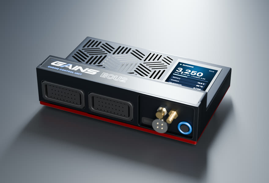
- Price TBA
ECU2Engine controller
6 cyl · port injection · drive-by-wire
Full sequential fuel and spark for this 6-cylinder, and its electronic throttle, with the wideband built in.
in designEst. availability: April 2027
Add PDM2 to switch and protect chassis loads (pumps, fans, lights, accessories). Add it in the configurator →
Track days? Add the Telemetry Dongle Pro for 25 Hz GPS lap timing; it plugs into the OBD-II port, and your phone is the dash. Plan it in the configurator →
What you get
- A screen on the ECUA 2.4-inch, 500-nit display in the lid, readable in a footwell.
- Faults in plain words"Coolant temp sensor open circuit.
- Drive-by-wire built inFour half-bridges run up to two electronic throttles, with pedal and throttle sensors on the ECU's own inputs and a windowed watchdog that cuts the motors in hardware on a fault.
- S3-style harnessesConnector A and C pin functions follow the published Nexus S3 wiring diagram.
- Powered CAN portA sealed 4-pin port on the insert carries 12 V and CAN for the PDM2 and GAINS displays: one cable per accessory.
- GAINS insideThe on-ECU adaptive layer, the app, logging and your limits.
How it wires in
- Haltech S3 plug-in harnessNone listed for this car
- Factory-connector → S3 adapter2 listed · from $960 USD listBF29083-S3
- Wire-inAlways possible
Pin-compatible per the published S3 pinout, not yet fit-tested. Every harness option for this car ↓
ECU2 is in design; specifications may change. All GAINS hardware is pre-release concept design; nothing is for sale yet and no application is validated on a vehicle. Harness fitment is from published pinouts and not yet fit-tested.
Swap guides
Into the IS300 / GS300 XE10 / S160
The 2JZ-GE (NA, VVT-i 1998+) family in other cars
How GAINS approaches the IS300 / GS300 XE10 / S160
Our starting method for this engine, as foundations first: get it running and drivable, then learn fuel, then the hardware-specific strategies. It is a methodology outline, not a validated calibration.
- 1Base map and first startplanned
Start from displacement, injector data and the sensors fitted, then let the first-start learner settle cranking, idle and warm-up before any load work. The goal is a safe, running engine, not a finished calibration.
- 2Lambda targets and VE learningclosed loop on GAINS ECUs
Air-fuel targets come from your goal (street, track, economy). The ECU then learns its fuel table cell by cell from the onboard wideband inside a signed envelope, and you approve promoting what it learned into the base map.
- 3Cam phasing (VVT)gated
Begin with conservative overlap. Cam targets per load cell are then chosen with torque and knock in mind, keeping idle and cold overlap low for stability. Widening cam authority follows the same evidence-gated path as spark.
- 4Drivability foundationsplanned
Pedal map, tip-in and decel fuel, idle control, cold start and warm-up enrichment: the tables tuners spend hours on after the main map. Each is a strategy in the knowledge engine with its own limits.
- 5Factory load sensingfactory reference
What the factory ECU measures load with: varies by year/market (low confidence); Forum: US/UK 2JZ-GE (Supra NA, SC300, GS300) uses MAF; JDM 2JZ-GE MAP. One poster claims Lexus used MAF in all markets. Unverified.
- 6Wideband sensorhardware
factory O2 type not yet sourced; plan on a Bosch LSU 4.9 for the GAINS ECU's built-in controller
Drivetrain
Chassis integration
- TRAC traction control standard
- VSC optional on automatic sedan, standard on SportCross
TRAC and VSC reduce torque through the electronic throttle and ignition, so they depend on communication between the chassis controllers and the engine ECM. Expect stability and traction functions, and their warning lamps, to be affected by any ECU replacement.
Tuning notes
2JZ-GE, 2,997 cc, 86 x 86 mm, 10.5:1, 215 hp (161 kW) at 5,800 rpm, 296 Nm at 3,800 rpm
Sourced1At 10.5:1 compression, forced induction on the IS300 needs conservative boost on pump fuel or an ethanol blend, careful intercooling and active knock monitoring. Many builders swap to a 2JZ-GTE instead to gain the turbo engine's lower compression and fuel system.
Popular swaps
2JZ-GTE swaps into the IS300 are common because the engine family is the same; the main issues are the drive-by-wire and immobilizer integration, the gearbox (the 5-speed manual or automatic behind the GE may not suit high torque), and turbo plumbing in the engine bay.
GAINS on the IS300 / GS300 XE10 / S160
ECU2
Designed so your phone is the laptop, keypad and dash
The GAINS app is designed to handle tuning, logging, gauges and switch inputs over Bluetooth, so the system needs no separate CAN keypad or display. Keypad, dash and logging views are planned; the iOS prototype runs on simulated data today.
Wideband, IMU and logging built in
An onboard Bosch LSU 4.9 wideband controller, a 6-axis IMU and onboard logging are designed into the ECU rather than sold as add-on modules.
Modular, so you buy what the engine needs
This engine runs on ECU2. PDM2 (power, body and gearbox) is optional and connects over ECU2's powered CAN port; the Telemetry Dongle Pro adds GPS lap timing from the OBD-II port.
Calibration that keeps learning
Instead of a fixed map that drifts as parts and conditions change, the ECU keeps adapting its fuel trims within limits you can see and approve in the app.
Adaptive tuning strategies
- VE learning closed loop on GAINS ECUs
Learns the fuel table from the onboard wideband as you drive, cell by cell, inside a signed authority envelope. Learned trims are promoted into the base map without a step in fuelling.
- Goal-based lambda targets closed loop on GAINS ECUs
Sets air-fuel targets from your goal (economy, response, power, safety margin) instead of a single fixed table.
- Knock protection protection
Listens for knock on a dedicated knock processor, pulls timing at once and restores it slowly. It only ever reduces advance.
- Warm-up, cranking, idle and transient fuel planned
The same learning approach applied to the tables tuners spend hours on after the main map is done.
- Spark advance and boost authority gated
Widening ignition advance or boost is never automatic. It stays an expert or dyno decision until validated knock detection exists for the engine family.
Already running another ECU? In advisor mode the same strategies read your logs and recommend exact table changes with the reasoning, which you apply in your ECU vendor's own software.
GAINS hardware is pre-release concept design. Simulated results only; nothing is validated on a vehicle yet.
Frequently asked
Is the IS300 drive-by-wire?
Yes. Lexus lists ETCS-i electronic throttle control for the IS300's 2JZ-GE.1
What compression ratio is the IS300 2JZ-GE?
10.5:1, with 86 x 86 mm bore and stroke (2,997 cc).1
Does the IS300 have an immobilizer?
Yes. Lexus lists a fully integrated theft deterrent system with an encoded vehicle immobilizer.1
Did the IS300 come with a manual transmission?
Yes, a 5-speed manual was available on the sedan; the automatic is a 5-speed ECT-i with E-shift.1
Does the IS300 have a limited-slip differential?
A Torsen LSD was standard on the SportCross and optional on the sedan.1
Sources
Numbered as cited above. Hover or tap a citation chip to preview it.
- 2002 Lexus IS 300 Specifications and Features · Lexus Canada (Toyota Canada Inc.) · oem · retrieved 2026-10-25
- Development of Toyota JZ Type Engine Series (SAE 930881), A. Tanke, T. Sugiyama, A. Kotani · SAE International · sae-paper · retrieved 2026-10-25
Catalog data and evidence
- Catalog data, not yet expert-reviewed.
- No vehicle photos: illustrations only until licensed imagery is available.
- Catalog note: Throttle type varies by model/year
- E-934 Boomslang identity (sourced, high confidence)
- E-935 Boomslang S3 catalog size (sourced, high confidence)
- E-900 Haltech Nexus S3 catalog (sourced, high confidence)
- E-941 S3 engine harness availability (inferred, medium confidence)
- E-1477 IS300 ECU (unverified-secondary, low confidence)