


Engine: K20A3 (EP3 Si, RSX base)
Part of the Honda K-series family.
Modeled power and torque
Modelled estimate, not a dyno result.
Modeled estimate, not a dyno measurement. Real results vary with fuel, weather, dyno type and build.
Stock is anchored to the factory rating (160 hp at 6500 rpm, 141 lb-ft at 4000 rpm); the curve shape between peaks is modeled. Intake + exhaust + tune (pump fuel): Typical NA gains come mostly above mid-rpm.
K20A3 (EP3 Si, RSX base) data
- Load sensing
- MAP speed-density
- O2 sensor
- wideband A/F (Honda/Denso A/F ratio sensor) upstream
- Closed loop
- A/F-sensor closed loop at part load; open loop enrichment at high load/WOT
- Block
- aluminium
- Rods / pistons
- Not yet sourced
- Reported limit
- Very wide spread: rod vendor (Hybrid Racing) says ~250-300 whp on stock rods; forum reports of ~550-600 whp on stock K24 bottom ends (forum anecdote, low confidence)
- Factory
- Honda top-feed (Keihin/Denso family; maker not confirmed)
- Impedance
- high (saturated)
- Direct-fit upgrades
- 6 maker-listed
- Knock
- Honda 30530-PPL-A01 (replaces 30530-PNA-003)
- MAP / MAF
- Honda 37830-PGK-A01
- O2 (upstream)
- Honda 36531-PND-A01 | Honda 36531-PND-A11
Platform background
The EP3 was the first K-series Civic Si. It is a Swindon-built three-door hatch with the 160 hp K20A3 economy i-VTEC engine in North America, a dash-mounted shifter and five-lug hubs. The European EP3 Type R used the K20A2 performance engine, which explains the large aftermarket for head and engine upgrades on the US car.
Factory ECU
Economy i-VTEC: VTC on intake, intake-side VTEC only (as on the base RSX K20A3)
Sourced · medium46OBD-II diagnostics (California required OBD II on essentially all 1996-and-later passenger cars)
Sourced1The factory PCM uses MAP-based load with an upstream A/F sensor, and handles VTC, VTEC and the immobilizer. Swapping K20A2/K20Z-series heads or complete engines in means re-calibrating VTC targets and the VTEC window, not just fuel.
Factory ECU: harness cross-reference
From the factory ECU each listed harness plugs into. The factory ECU is unplugged, not modified. Check the label and part number on your own ECU before ordering.
- ECU family
- Honda 37820-PRB / PND / PRC family
- Applies to
- Civic EP3 2002-05; Integra DC5 / RSX 2002-04; manual
- Not for
- automatic; 05-06 RSX (use HT-186342)
PRB = RSX Type S K20A2 6MT; PND-A53 = 02-04 RSX base; JDM DC5 Type R uses 37820-PRC. EP3 part number not found.
- ECU family
- Honda K-series (PRB)
- Applies to
- 2002-04 RSX (Type-S K20A2 examples), 2002-05 Civic Si; manual
- Not for
- Base RSX (K20A3) and Civic Si use different codes - confirm
Numbers are Type-S examples from used-parts listings.
Factory ECU pinout
Each connector face drawn from the OEM service manual's pin data, with every terminal's function and wire colour where the manual prints it.
Honda K-series ECM/PCM, 2002-04 Acura RSX and 2002-03 Civic Si (EP3)
The 2002-04 Acura RSX (K20A2 Type S and K20A3 base) uses a Honda ECM (manual) or PCM (automatic) with connectors A (31P), B (24P) and E (31P) carrying the engine, plus C (22P) and D (17P) on automatic cars for the transmission. The 2002-03 Civic Si (EP3, K20A3) ECM uses the same A, B and E layout with a few cavities unused. That is 125 cavities with all five connectors fitted.
2002-2004 (RSX); 2002-2003 Civic Si confirmed · US · 5 connectors, 125 cavities · 96 terminals sourced
Looking into the ECU's connector. The harness plug seen from its wire side has the same layout.
How the OEM figure is oriented
The OEM figure is captioned 'Wire side of female terminals': the harness plug seen from the wire-entry side, lock boss up, terminal 1 at top left. That orientation matches looking into the ECM/PCM header, so the cells are stored as printed and tagged ecu-side; mirror horizontally for the plug's mating face.| Pin | Function | Type | Wire | Notes |
|---|---|---|---|---|
| 1 | A/F sensor heater control (AFSHTC) | low-side heater driver | BLK/WHT | |
| 2 | Power source, ignition switched (IGP2) | 12 V switched supply | YEL/BLK | |
| 3 | Power source, ignition switched (IGP1) | 12 V switched supply | YEL/BLK | |
| 4 | Power ground (PG2) | chassis ground | BLK | |
| 5 | Power ground (PG1) | chassis ground | BLK | |
| 6 | A/F (wideband) sensor 1, + side (AFS+) | A/F sensor cell signal | RED | |
| 7 | Crankshaft position sensor (CKP) | crank position pulses | BLU | |
| 8 | Intake manifold runner control valve position sensor (IMTVPS / IMRCVPS) | 0-5 V analog (about 3.75 V below 4,700 rpm, 1.25 V above) | RED/YEL | RSX K20A3 engine only (manual footnote). Drawn slashed (unused) on the 2002-03 Civic Si (EP3) face view; not used on the RSX K20A2. |
| 9 | Knock sensor (KS) | knock sensor signal | RED/BLU | |
| 10 | Sensor ground (SG2) | sensor ground | GRN/YEL | |
| 11 | Sensor ground (SG1) | sensor ground | GRN/WHT | |
| 12 | Idle air control valve (IACV) | duty-controlled driver | BLK/RED | |
| 15 | Throttle position sensor (TPS) | 0-5 V analog (about 0.5 V closed, 4.8 V wide open) | RED/BLK | |
| 16 | A/F (wideband) sensor 1, - side (AFS-) | A/F sensor cell signal | RED/YEL | |
| 18 | Vehicle speed sensor (VSS) | pulse input (0 V to 5 V or battery voltage) | WHT/GRN | RSX manual footnote: M/T. Listed without a footnote in the 2002-03 Civic Si manual (Civic Si is M/T only). |
| 19 | Manifold absolute pressure sensor (MAP) | 0-5 V analog (about 3.0 V key on, 1.0 V at idle) | GRN/RED | |
| 20 | Sensor 5 V supply (VCC2) | 5 V reference | YEL/BLU | |
| 21 | Sensor 5 V supply (VCC1) | 5 V reference | YEL/RED | |
| 22 | A/F sensor heater, + side voltage detect (AFSHTC+) | heater supply voltage sense (battery voltage key on) | WHT | |
| 23 | Logic ground (LG2) | ECM logic ground | BRN/YEL | |
| 24 | Logic ground (LG1) | ECM logic ground | BRN/YEL | |
| 25 | Camshaft position sensor A (CMPA) | cam position pulses | BLU/WHT | |
| 26 | Camshaft position sensor B (CMPB) | cam position pulses | GRN | The 2002-03 Civic Si manual labels it CMPB (TDC), camshaft position sensor B (top dead centre sensor). |
| 27 | Ignition coil No. 4 pulse (IGPLS4) | coil trigger pulse (coil-on-plug with igniter) | BRN | |
| 28 | Ignition coil No. 3 pulse (IGPLS3) | coil trigger pulse (coil-on-plug with igniter) | WHT/BLU | |
| 29 | Ignition coil No. 2 pulse (IGPLS2) | coil trigger pulse (coil-on-plug with igniter) | BLU/RED | |
| 30 | Ignition coil No. 1 pulse (IGPLS1) | coil trigger pulse (coil-on-plug with igniter) | YEL/GRN |
Our drawing from published pin data; not an OEM drawing. Layout from the OEM face view (high confidence). Confirm against the factory manual for your exact year and market before cutting or pinning wires.
Looking into the ECU's connector. The harness plug seen from its wire side has the same layout.
How the OEM figure is oriented
The OEM figure is captioned 'Wire side of female terminals': the harness plug seen from the wire-entry side, lock boss up, terminal 1 at top left. That orientation matches looking into the ECM/PCM header, so the cells are stored as printed and tagged ecu-side; mirror horizontally for the plug's mating face.| Pin | Function | Type | Wire | Notes |
|---|---|---|---|---|
| 1 | VTC oil control solenoid valve, + side (VTC+) | solenoid driver | BLU/WHT | |
| 2 | Injector No. 4 (INJ4) | low-side injector driver | YEL | |
| 3 | Injector No. 3 (INJ3) | low-side injector driver | BLU | |
| 4 | Injector No. 2 (INJ2) | low-side injector driver | RED | |
| 5 | Injector No. 1 (INJ1) | low-side injector driver | BRN | |
| 6 | Radiator fan control (FANC) | low-side relay driver | GRN | |
| 7 | Reverse lock solenoid valve (RVS) | solenoid driver | GRN/WHT | RSX manual footnote: K20A2 engine. Listed without a footnote in the 2002-03 Civic Si manual. |
| 8 | Engine coolant temperature sensor (ECT) | 0-5 V analog thermistor (about 0.1-4.8 V) | RED/WHT | |
| 9 | VTEC oil pressure switch (VTPSW, rocker arm oil pressure switch) | switch input (0 V low rpm, battery voltage in VTEC) | BLU/BLK | |
| 10 | Alternator L signal (ALTL) | alternator lamp / L terminal input | WHT/BLU | |
| 13 | Alternator FR signal (ALTF) | alternator field-duty input (0-5 V) | WHT/RED | |
| 14 | A/T clutch pressure control solenoid valve A, + side (LSA+) | current-controlled solenoid driver | RED/BLK | A/T only (manual footnote). |
| 15 | VTEC solenoid valve (VTS, rocker arm oil control solenoid) | solenoid driver | GRN/YEL | |
| 16 | A/T clutch pressure control solenoid valve B, + side (LSB+) | current-controlled solenoid driver | BRN/WHT | A/T only (manual footnote). |
| 17 | Intake air temperature sensor (IAT) | 0-5 V analog thermistor (about 0.1-4.8 V) | RED/YEL | |
| 18 | Alternator control (ALTC) | alternator control output (0-5 V) | WHT/GRN | |
| 21 | EVAP canister purge valve (PCS) | duty-controlled solenoid driver | YEL/BLU | |
| 22 | Intake manifold runner control solenoid valve (IMT / IMRC) | solenoid driver (switches at 4,700 rpm) | RED/BLU | RSX K20A3 engine only (manual footnote). Drawn slashed (unused) on the 2002-03 Civic Si face view. |
| 23 | VTC oil control solenoid valve, - side (VTC-) | solenoid return | BLK/WHT | |
| 24 | A/T clutch pressure control solenoid valve C, + side (LSC+) | current-controlled solenoid driver | BLU/YEL | A/T only (manual footnote). |
Our drawing from published pin data; not an OEM drawing. Layout from the OEM face view (high confidence). Confirm against the factory manual for your exact year and market before cutting or pinning wires.
Looking into the ECU's connector. The harness plug seen from its wire side has the same layout.
How the OEM figure is oriented
The OEM figure is captioned 'Wire side of female terminals': the harness plug seen from the wire-entry side, lock boss up, terminal 1 at top left. That orientation matches looking into the ECM/PCM header, so the cells are stored as printed and tagged ecu-side; mirror horizontally for the plug's mating face.| Pin | Function | Type | Wire | Notes |
|---|---|---|---|---|
| 1 | A/T clutch pressure control solenoid valve A, - side (LSA-) | solenoid return | WHT/BLK | A/T PCM only (connector heading footnote). |
| 2 | Shift solenoid valve C (SHC) | solenoid driver | GRN | A/T PCM only (connector heading footnote). |
| 3 | Shift solenoid valve E (SHE) | solenoid driver | YEL | A/T PCM only (connector heading footnote). |
| 4 | Shift solenoid valve B (SHB) | solenoid driver | GRN/WHT | A/T PCM only (connector heading footnote). |
| 5 | Shift solenoid valve D (SHD) | solenoid driver | GRN/RED | A/T PCM only (connector heading footnote). |
| 6 | Shift solenoid valve A (SHA) | solenoid driver | BLU/BLK | A/T PCM only (connector heading footnote). |
| 7 | Input shaft (mainshaft) speed sensor (NM) | speed pulses | WHT/RED | A/T PCM only (connector heading footnote). |
| 8 | A/T clutch pressure control solenoid valve B, - side (LSB-) | solenoid return | BLK/RED | A/T PCM only (connector heading footnote). |
| 9 | Transmission range switch D3 position (ATPD3) | switch input (0 V in D3) | RED | A/T PCM only (connector heading footnote). |
| 10 | 3rd clutch oil pressure switch (OP3SW) | switch input | BLU/WHT | A/T PCM only (connector heading footnote). |
| 12 | Transmission range switch R position (ATPRVS) | switch input (0 V in R) | RED/WHT | A/T PCM only (connector heading footnote). |
| 13 | 2nd clutch oil pressure switch (OP2SW) | switch input | BLU/RED | A/T PCM only (connector heading footnote). |
| 14 | ATF temperature sensor (ATFT) | 0-5 V analog thermistor (about 0.2-4.8 V) | RED/YEL | A/T PCM only (connector heading footnote). |
| 15 | Output shaft (countershaft) speed sensor (NC) | speed pulses | BLU | A/T PCM only (connector heading footnote). |
| 16 | A/T clutch pressure control solenoid valve C, - side (LSC-) | solenoid return | WHT/BLU | A/T PCM only (connector heading footnote). |
| 18 | Transmission range switch D/D3 position (ATPFWD) | switch input (0 V in D or D3) | BLU/YEL | A/T PCM only (connector heading footnote). |
Our drawing from published pin data; not an OEM drawing. Layout from the OEM face view (high confidence). Confirm against the factory manual for your exact year and market before cutting or pinning wires.
Looking into the ECU's connector. The harness plug seen from its wire side has the same layout.
How the OEM figure is oriented
The OEM figure is captioned 'Wire side of female terminals': the harness plug seen from the wire-entry side, lock boss up, terminal 1 at top left. That orientation matches looking into the ECM/PCM header, so the cells are stored as printed and tagged ecu-side; mirror horizontally for the plug's mating face.| Pin | Function | Type | Wire | Notes |
|---|---|---|---|---|
| 2 | Sequential SportShift mode switch (S-MODE) | switch input (0 V in SportShift mode) | BRN | A/T PCM only (connector heading footnote). |
| 3 | Upshift switch (S-UP) | switch input | WHT/BLU | A/T PCM only (connector heading footnote). |
| 4 | Transmission range switch N position (ATPN) | switch input (0 V in N) | BLK/RED | A/T PCM only (connector heading footnote). |
| 5 | Transmission range switch R position (ATPR) | switch input (0 V in R) | WHT | A/T PCM only (connector heading footnote). |
| 6 | Transmission range switch P position (ATPP) | switch input (0 V in P) | BLU/BLK | A/T PCM only (connector heading footnote). |
| 9 | Downshift switch (S-DN) | switch input | BRN/WHT | A/T PCM only (connector heading footnote). |
| 10 | Transmission range switch D position (ATPD) | switch input (0 V in D) | RED | A/T PCM only (connector heading footnote). |
| 12 | Cruise control signal (CCS) | pulse signal to/from cruise control unit | BLU/ORN | A/T PCM only (connector heading footnote). |
Our drawing from published pin data; not an OEM drawing. Layout from the OEM face view (high confidence). Confirm against the factory manual for your exact year and market before cutting or pinning wires.
Looking into the ECU's connector. The harness plug seen from its wire side has the same layout.
How the OEM figure is oriented
The OEM figure is captioned 'Wire side of female terminals': the harness plug seen from the wire-entry side, lock boss up, terminal 1 at top left. That orientation matches looking into the ECM/PCM header, so the cells are stored as printed and tagged ecu-side; mirror horizontally for the plug's mating face.| Pin | Function | Type | Wire | Notes |
|---|---|---|---|---|
| 1 | Immobilizer fuel pump relay, drives PGM-FI main relay 2 (IMOFPR) | low-side relay driver | GRN/YEL | |
| 2 | Secondary heated oxygen sensor, sensor 2 (SHO2S) | 0-1 V narrowband O2 signal | WHT/RED | |
| 3 | Logic ground (LG3) | ECM logic ground | BRN/YEL | |
| 4 | Sensor ground (SG3) | sensor ground | PNK | |
| 5 | Sensor 5 V supply (VCC3) | 5 V reference | YEL/BLU | The 2002-03 Civic Si face view draws cavity 5 slashed, but its terminal table lists 5 = VCC3 (YEL/BLU). Treat the table as authoritative and check the cavity before wiring. |
| 6 | Secondary HO2S heater control (SHO2SHTC) | low-side heater driver | BLK/WHT | |
| 7 | PGM-FI main relay 1 drive (MRLY); also power source for DTC memory | low-side relay driver | RED/YEL | |
| 8 | A/F sensor heater control relay (AFSHTCR) | low-side relay driver | ORN | |
| 9 | Ignition signal (IG1) | 12 V ignition-switched input | BLK/YEL | |
| 13 | Shift lock control (SLC) | shift lock control signal | WHT/BLU | A/T only (manual footnote). The RSX face view labels this cavity ILU while the table names it SLC; the table is used here. Drawn slashed on the 2002-03 Civic Si face. |
| 14 | Fuel tank pressure sensor (FTP) | 0-5 V analog (about 2.5 V with fuel cap open) | LT GRN | |
| 15 | Electrical load detector (ELD) | 0-5 V analog (about 0.1-4.8 V) | GRN/RED | |
| 16 | Power steering pressure switch (PSPSW, RSX) / electrical power steering load detect (EPSLD, Civic Si) | switch input | LT GRN/BLK | Same cavity and wire colour on both cars; the RSX has a hydraulic power steering pressure switch, the 2002-03 Civic Si an EPS load-detect signal from the EPS unit. |
| 18 | A/C clutch relay (ACC) | low-side relay driver | RED | |
| 20 | EVAP bypass solenoid valve (2WBS) | solenoid driver | BLU/RED | |
| 21 | EVAP canister vent shut valve (VSV) | solenoid driver | LT GRN/RED | |
| 22 | Brake pedal position switch (BKSW) | 12 V switch input (battery voltage when pressed) | WHT/BLK | |
| 23 | K-line, scan tool communication (K-LINE) | ISO K-line to DLC | LT BLU | |
| 24 | Multiplex control unit communication (SEFMJ) | serial link to multiplex control unit | YEL | |
| 25 | Vehicle speed sensor output (VSSOUT) | VSS pulse output | BLU/WHT | A/T only (manual footnote). Drawn slashed on the 2002-03 Civic Si face. |
| 26 | Engine speed pulse output (NEP) | tach pulse output | BLU | |
| 27 | Immobilizer code (IMOCD) | immobilizer serial input | RED/BLU | |
| 29 | Service check signal (SCS) | diagnostic input (shorted to ground with the HDS / PGM Tester) | BRN | |
| 30 | Write enable signal (WEN) | reprogramming enable input | RED/WHT | |
| 31 | Malfunction indicator lamp (MIL) | low-side lamp driver | GRN/ORN |
Our drawing from published pin data; not an OEM drawing. Layout from the OEM face view (high confidence). Confirm against the factory manual for your exact year and market before cutting or pinning wires.
Coverage, year splits and safety
Year split: the RSX manual gives a completely different terminal assignment for 2005-2006 models on the same connector shells (see the separate 2005-06 RSX entry). The catalog row acura-rsx-dc5-base-k20a3 covers 2002-06, so use this page only for 2002-04 base cars.
Civic Si (EP3): the cited Civic manual covers 2002-2003 and shows an M/T-only ECM with connectors A, B and E. Its pins match the RSX table except: A8 and B22 unused (no intake runner control), B14/B16/B24 and E13/E25 unused (automatic-only on the RSX), and E16 is an electric power steering load signal. 2004-05 Civic Si pages were not checked.
Footnoted pins: A8 and B22 are RSX K20A3 only; B7 (reverse lock solenoid) is RSX K20A2 only; A18 (VSS) is listed for M/T; B14, B16, B24, E13, E25 and all of connectors C and D are A/T only. The EU Civic Type R (K20A2) and JDM Integra Type R ECUs are not covered here.
Signal descriptions summarise Honda's measuring conditions, not test limits. Before probing or re-pinning, disconnect the battery negative, and back-probe only from the wire side with a fine probe; never force a sharp probe into the terminal face or past a seal.
Plug-and-play harness
A plug-in harness built for the Haltech Nexus S3 pinout is listed for this vehicle. The ECU2 follows that published pinout, so the factory ECU is unplugged and the ECU2 plugs into the car's own loom. Nothing is written to the factory ECU. Pin-compatible per the published S3 pinout, not yet fit-tested.
| Maker | Harness | Fits | Link | |
|---|---|---|---|---|
 | Nexus S2/S3 Plug n Play Adapter Harness Honda EP3HT-186343 | Civic EP3 2002-05; Integra DC5 / RSX 2002-04; manual | $535Lowest | Maker ↗ |
 | Manual 2002 - 2004 Acura RSXBF29008-S3 | 2002-04 RSX (Type-S K20A2 examples), 2002-05 Civic Si; manual | $840 | Maker ↗ |
| Wire-in | Universal flying lead or re-terminated factory harness | Any engine (terminate to ECU2's two Superseal 34 connectors) | Universal harness from $405 | Maker ↗ |
Nexus S2/S3 Plug n Play Adapter Harness Honda EP3
- Plugs into
Honda K20 ECU (EP3 02-05 / DC5-RSX 02-04) · 37820-PRB-A05, 37820-PRB-A06…
- OEM part numbers
- 37820-PRB-A05, 37820-PRB-A06, 37820-PND-A53
- ECU
- Honda 37820-PRB / PND / PRC family
- Confidence
- low
PRB = RSX Type S K20A2 6MT; PND-A53 = 02-04 RSX base; JDM DC5 Type R uses 37820-PRC. EP3 part number not found.
Sources: E-1450
- Fits
- Civic EP3 2002-05; Integra DC5 / RSX 2002-04; manual
- Exclusions
- automatic; 05-06 RSX (use HT-186342)
- SKU
- HT-186343
- Maker fitment
- Honda Civic EP3 02-05 and Integra DC5 / Acura RSX 02-04; manual only; no multiplexed coolant gauge, battery light or AC request
- Maker notes
- kit HT-213302
Boomslang plug-and-play harness for Haltech Nexus S3 - Manual 2002 - 2004 Acura RSX
- Plugs into
Honda K-series ECM (2002-04 RSX / 2002-05 Civic Si EP3) · 37820-PRB-A03, 37820-PRB-A06…
- OEM part numbers
- 37820-PRB-A03, 37820-PRB-A06, 37820-PRB-A08
- ECU
- Honda K-series (PRB)
- Confidence
- low
Numbers are Type-S examples from used-parts listings.
Sources: E-1464
- Fits
- 2002-04 RSX (Type-S K20A2 examples), 2002-05 Civic Si; manual
- Exclusions
- Base RSX (K20A3) and Civic Si use different codes - confirm
- SKU
- BF29008-S3
- Maker fitment
- Acura RSX; Honda Civic (Manual); selector years 2001-2005; SKU label: Manual 2002 - 2004 Acura RSX
- Maker notes
- separate SKUs exist for other Nexus models (-S2/-R3/-R5/-T1/-T2)
Haltech and Boomslang are trademarks of their respective owners. GAINS is not affiliated with or endorsed by them.
Your GAINS system for this car · pre-release
ECU2 for the Civic Si EP3
Planned with the same rules as the configurator for this car's 4 cyl · port injection · cable throttle. The factory ECU is unplugged and replaced; nothing is written to it.

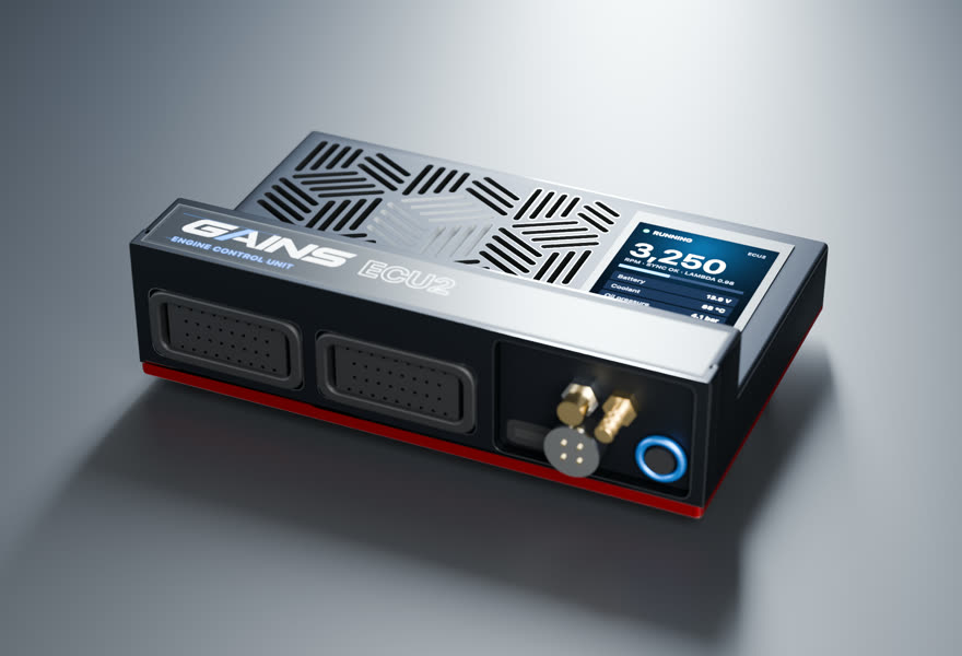
- Price TBA
ECU2Engine controller
4 cyl · port injection · cable throttle
Full sequential fuel and spark for this 4-cylinder on a cable throttle, with the wideband built in.
in designEst. availability: April 2027
Add PDM2 to switch and protect chassis loads (pumps, fans, lights, accessories). Add it in the configurator →
Track days? Add the Telemetry Dongle Pro for 25 Hz GPS lap timing; it plugs into the OBD-II port, and your phone is the dash. Plan it in the configurator →
What you get
- A screen on the ECUA 2.4-inch, 500-nit display in the lid, readable in a footwell.
- Faults in plain words"Coolant temp sensor open circuit.
- S3-style harnessesConnector A and C pin functions follow the published Nexus S3 wiring diagram.
- Powered CAN portA sealed 4-pin port on the insert carries 12 V and CAN for the PDM2 and GAINS displays: one cable per accessory.
- GAINS insideThe on-ECU adaptive layer, the app, logging and your limits.
How it wires in
- Haltech S3 plug-in harness1 listed · from $535 USD listHT-186343
- Factory-connector → S3 adapter1 listed · from $840 USD list
- Wire-inAlways possible
Pin-compatible per the published S3 pinout, not yet fit-tested. Every harness option for this car ↓
ECU2 is in design; specifications may change. All GAINS hardware is pre-release concept design; nothing is for sale yet and no application is validated on a vehicle. Harness fitment is from published pinouts and not yet fit-tested.
Swap guides
The K20A3 (EP3 Si, RSX base) family in other cars
How GAINS approaches the Civic Si EP3
Our starting method for this engine, as foundations first: get it running and drivable, then learn fuel, then the hardware-specific strategies. It is a methodology outline, not a validated calibration.
- 1Base map and first startplanned
Start from displacement, injector data and the sensors fitted, then let the first-start learner settle cranking, idle and warm-up before any load work. The goal is a safe, running engine, not a finished calibration.
- 2Lambda targets and VE learningclosed loop on GAINS ECUs
Air-fuel targets come from your goal (street, track, economy). The ECU then learns its fuel table cell by cell from the onboard wideband inside a signed envelope, and you approve promoting what it learned into the base map.
- 3VTEC crossoverplanned
VTEC engagement is treated as a load and rpm surface where the two cam profiles cross on torque, learned from logs rather than a single fixed rpm.
- 4Cam phasing (VVT)gated
Begin with conservative overlap. Cam targets per load cell are then chosen with torque and knock in mind, keeping idle and cold overlap low for stability. Widening cam authority follows the same evidence-gated path as spark.
- 5Drivability foundationsplanned
Pedal map, tip-in and decel fuel, idle control, cold start and warm-up enrichment: the tables tuners spend hours on after the main map. Each is a strategy in the knowledge engine with its own limits.
- 6Factory load sensingfactory reference
What the factory ECU measures load with: MAP speed-density (medium confidence)
- 7Wideband sensorhardware
the factory sensor is already an A/F type; for tuning, fit a Bosch LSU 4.9 for the GAINS ECU's built-in controller (factory A/F sensors are not LSU-compatible)
- 8Bottom end and head sealingfactory reference
Reported: Stock rods and especially rod bolts are commonly reported as the first bottom-end limit under boost (vendor and forum consensus); some builders also add sleeves or a block guard because the block is open-deck (single forum opinion). (low confidence) Limits depend on tune quality, fuel, rpm and condition and are not guaranteed.
Drivetrain
Chassis integration
Tuning notes
Common upgrades are intake, header and exhaust, then a K20A2/K20Z-series head or a complete K20A2/K24 engine. Because the US engine is an economy i-VTEC design, a performance-head conversion changes the VTEC system on the exhaust side, so the ECU calibration must support it.
Popular swaps
GAINS on the Civic Si EP3
ECU2
Designed so your phone is the laptop, keypad and dash
The GAINS app is designed to handle tuning, logging, gauges and switch inputs over Bluetooth, so the system needs no separate CAN keypad or display. Keypad, dash and logging views are planned; the iOS prototype runs on simulated data today.
Wideband, IMU and logging built in
An onboard Bosch LSU 4.9 wideband controller, a 6-axis IMU and onboard logging are designed into the ECU rather than sold as add-on modules.
Modular, so you buy what the engine needs
This engine runs on ECU2. PDM2 (power, body and gearbox) is optional and connects over ECU2's powered CAN port; the Telemetry Dongle Pro adds GPS lap timing from the OBD-II port.
Calibration that keeps learning
Instead of a fixed map that drifts as parts and conditions change, the ECU keeps adapting its fuel trims within limits you can see and approve in the app.
Adaptive tuning strategies
- VE learning closed loop on GAINS ECUs
Learns the fuel table from the onboard wideband as you drive, cell by cell, inside a signed authority envelope. Learned trims are promoted into the base map without a step in fuelling.
- Goal-based lambda targets closed loop on GAINS ECUs
Sets air-fuel targets from your goal (economy, response, power, safety margin) instead of a single fixed table.
- Knock protection protection
Listens for knock on a dedicated knock processor, pulls timing at once and restores it slowly. It only ever reduces advance.
- Warm-up, cranking, idle and transient fuel planned
The same learning approach applied to the tables tuners spend hours on after the main map is done.
- Spark advance and boost authority gated
Widening ignition advance or boost is never automatic. It stays an expert or dyno decision until validated knock detection exists for the engine family.
Already running another ECU? In advisor mode the same strategies read your logs and recommend exact table changes with the reasoning, which you apply in your ECU vendor's own software.
GAINS hardware is pre-release concept design. Simulated results only; nothing is validated on a vehicle yet.
Frequently asked
What engine is in the EP3 Civic Si?
The K20A3 2.0-litre i-VTEC, rated at 160 hp and 132 lb-ft.5
Is the EP3 Si K20A3 the same as the RSX Type-S engine?
No. The K20A3 is the economy i-VTEC version with intake-only VTEC. The RSX Type-S K20A2 switches both cams and runs higher compression.46
Where was the EP3 built?
Swindon, England.5
What engine did the European EP3 Type R use?
The K20A2.6
Sources
Numbered as cited above. Hover or tap a citation chip to preview it.
- California Air Resources Board OBD II staff report (1996 rulemaking) · California Air Resources Board · press · retrieved 2026-10-25
- EFK K-Series Mount Kit (88-91 Civic/CRX) · Hasport Performance · vendor-doc · retrieved 2026-10-25
- EGK K-Series Mount Kit (92-95 Civic, 94-01 Integra, Del Sol) · Hasport Performance · vendor-doc · retrieved 2026-10-25
- 2002 Acura RSX Powertrain · American Honda Motor Co. (hondanews.com) · press · retrieved 2026-10-25
- Honda Civic Si Timeline and Milestones · American Honda Motor Co. (hondanews.com) · press · retrieved 2026-10-25
- Honda K engine · Wikipedia · community · retrieved 2026-10-25
Catalog data and evidence
- Catalog data, not yet expert-reviewed.
- No vehicle photos: illustrations only until licensed imagery is available.
- E-923 Haltech S3 adapter harness page (sourced, high confidence)
- E-9302 K-series harness/ECU xref: H3 (sourced, medium confidence)
- E-934 Boomslang identity (sourced, high confidence)
- E-935 Boomslang S3 catalog size (sourced, high confidence)
- E-900 Haltech Nexus S3 catalog (sourced, high confidence)
- E-941 S3 engine harness availability (inferred, medium confidence)
- E-1450 Honda K20 RSX ECU (reported, low confidence)
- E-1464 RSX ECM (unverified-secondary, low confidence)