

Bosch · Variable reluctance (VR, AC)
Bosch IS-C inductive (VR) speed sensor
The Bosch IS-C is an inductive (variable reluctance) speed sensor for crankshaft or wheel speed, rated to 15 kHz and 230 °C at the sensing head. It needs a 0.8 ± 0.3 mm air gap to a ferromagnetic wheel, has a 340 Ω coil, and its connector carries Sig+, ground and a screen (shield) pin.1
Key specifications
Measures: Tooth passing on a ferromagnetic trigger wheel (speed and position). Output: Variable reluctance (VR, AC).
Pinout and connector
- Supply
- Ground / return
- Signal
- Shield
- Not used / not listed
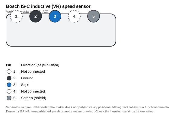
| Pin | Function (as published) | Typical ECU input | Wire note |
|---|---|---|---|
| 1 | Not connected | Leave unconnected | — |
| 2 | Ground | Sensor ground | Twisted, shielded pair |
| 3 | Sig+ | Crank/cam trigger input (VR) | Twisted, shielded pair |
| 4 | Not connected | Leave unconnected | — |
| 5 | Screen (shield) | Shield drain to sensor ground at the ECU end only | Twisted, shielded pair |
Pin functions as published.1 The ECU-input and wire columns are our general guidance, not the maker's.
Connector: ASL 6-06-05SN-HE; mating part F 02U 000 237-01 (ASL 0-06-05PN-HE)1 Connector library
Terminals and seals: Not listed: the Bosch data sheet gives the mating housing only, not contact or seal part numbers.
How it's calibrated
ECU-neutral: enter these values in whichever ECU you use. Nominal values without the maker's tolerance band.
Trigger setup
Native support across ECUs
| ECU platform | Status | How to set it up | Source |
|---|---|---|---|
| GAINS ECU2Concept | Configurable (generic input) | CRANK (pin 13) or CAM (pin 15): VR or Hall, single-ended, adaptive threshold; shielded cable with the shield at sensor ground. Concept hardware. | Medium2 |
| Haltech (Elite / Nexus) | Configurable (generic input) | Trigger or Home input; Haltech's wiring diagram lists reluctor (VR) support. | 5 |
| Link (G4X) | Unverified | Link's G4X page does not state VR support; its VR sensor page names no ECU model. | No public source |
| MoTeC (M1) | Unverified | The M150 page lists programmable digital trigger inputs but does not name VR sensors. | No public source |
| ECUMaster (EMU Black) | Configurable (generic input) | Trigger input (3: primary and 2 cams), Hall or VR selected in software. | 6 |
| AEM (Infinity) | Configurable (generic input) | Differential VR input. | 7 |
| MaxxECU | Configurable (generic input) | Trigger input (VR or digital) on the RACE. | 8 |
| Holley (Terminator X / EFI) | Configurable (generic input) | Crank or cam input. Holley recommends Hall sensors and asks for shielded cable with magnetic (VR) pickups. | Medium9 |
Third-party rows come only from each vendor's public product pages, sensor lists and spec sheets, retrieved on the dates listed in Sources; we do not use ECU software, help files, base maps or calibration files, and reproduce no vendor calibration values. "Preset listed" means the vendor publicly names this sensor; "Configurable" means a matching generic input is listed. Check the vendor's current documentation before buying.
Trademarks belong to their owners. Names are used only to identify compatible products; no endorsement is implied.
CAD and drawings
- Data sheetInductive Speed Sensor IS-C data sheet (PDF)1Download from Bosch MotorsportNo login at last check; the maker may change this
We link to the maker's own downloads and do not rehost their CAD or data sheets: the maker's terms do not grant redistribution. Registration may be needed on the maker's site.
Wiring and installation
Run Sig+ and ground as a twisted pair inside the screen; ground the screen at the ECU end only.Medium142
Bosch notes that a wheel of different dimensions needs individual testing.1
Failure modes and checks
Likely cause Air gap too large
Check Set 0.8 ± 0.3 mm.Medium1
Test it with a multimeter
- Unplugged, measure across Sig+ and ground: about 340 Ω coil resistance. Spinning the engine should show a small AC voltage that rises with speed.1
Frequently asked
Related
Use it with GAINS
Bosch IS-C inductive (VR) speed sensor on GAINS hardware
GAINS hardware is pre-release concept design; pin numbers can change before release and none of it has been tested on a vehicle yet.23
Concept Pre-release hardware. Pin assignments come from the current design documents and may change.
Sources
9 sources
- Inductive Speed Sensor IS-C data sheet · Bosch Motorsport (Bosch Engineering GmbH) · vendor-doc · retrieved 2026-10-27
- internal GAINS internal: ECU2 concept and pin map v0.3 (hardware/mini-ecu/CONCEPT.md §3)
- internal GAINS internal: PDM2 input and output specification (hardware/mini-pdm/SPEC.md)
- Shielded cable · Wikipedia · reference · retrieved 2026-10-27
- Nexus R3 wiring diagram (HT-193000_WD) · Haltech · vendor-doc · retrieved 2026-10-27
- EMU Black product page · ECUMaster · vendor-doc · retrieved 2026-10-27
- Infinity Series 5 hardware specification · AEM Electronics · vendor-doc · retrieved 2026-10-27
- MaxxECU RACE product page · MaxxECU · vendor-doc · retrieved 2026-10-27
- HP / Dominator EFI wiring manual 199R10555 · Holley · vendor-doc · retrieved 2026-10-27
Not yet indexed: fewer than 3 FAQs.