

Bosch · Potentiometer 0-5 V
Bosch 0 280 750 149 electronic throttle body (40 mm)
Bosch 0 280 750 149 is Bosch Motorsport's 40 mm electronic throttle body. It flows up to 695 kg/h (25.5 lb/min) at 85° in Bosch's test, weighs 0.9 kg (2.0 lb), and uses a 6-pin connector: motor on pins 1 and 4, sensor 5 V on pin 3, ground on pin 2 and signals on pins 5 and 6.12
Key specifications
Measures: Throttle plate angle (two redundant tracks); motor-driven throttle actuator. Output: Potentiometer 0-5 V.
Pinout and connector
- Supply
- Ground / return
- Signal
- Shield
- Not used / not listed
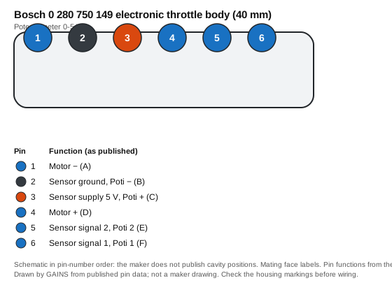
| Pin | Function (as published) | Typical ECU input | Wire note |
|---|---|---|---|
| 1 | Motor − (A) | Analog voltage input (pull-up off) | — |
| 2 | Sensor ground, Poti − (B) | Sensor ground | Return to sensor ground, not chassis |
| 3 | Sensor supply 5 V, Poti + (C) | +5 V sensor reference | — |
| 4 | Motor + (D) | Analog voltage input (pull-up off) | — |
| 5 | Sensor signal 2, Poti 2 (E) | Analog voltage input (pull-up off) | — |
| 6 | Sensor signal 1, Poti 1 (F) | Analog voltage input (pull-up off) | — |
From Bosch's pin-layout sheet for the 40 mm body. Drawn in pin-number order, not as the physical cavity layout.2 The ECU-input and wire columns are our general guidance, not the maker's.
Connector: Bosch 6-pin (AMP) throttle body connector; mating part D 261 205 358-0124 Connector library
Terminals and seals: Sold with the mating housing by Bosch Motorsport; terminal numbers not listed on the pages cited.
Transfer function and calibration data
Output I = 5 V × angle / 90°; Output II = 5 V − Output I
Nominal end points from Bosch Motorsport's data sheet; the ECU learns the actual end stops.
Show the 3 data points
| Throttle angle (°) | Output I (V) |
|---|---|
| 0 | 0 |
| 45 | 2.5 |
| 90 | 5 |
How it's calibrated
ECU-neutral: enter these values in whichever ECU you use. Nominal values without the maker's tolerance band.
Transfer function
- 0–5 V → 0–90 ° (maker: Output I = 5 V × angle / 90°; Output II = 5 V − Output I)1
Worked conversion
- At 2.5 V the output corresponds to 45 °.1Calculated from the maker's data
Throttle position outputs: output voltage to throttle angle (11 rows)Calculated from the maker's data
| Output (V) | Throttle angle (°) |
|---|---|
| 0 | 0 |
| 0.5 | 9 |
| 1 | 18 |
| 1.5 | 27 |
| 2 | 36 |
| 2.5 | 45 |
| 3 | 54 |
| 3.5 | 63 |
| 4 | 72 |
| 4.5 | 81 |
| 5 | 90 |
Interpolated between the maker's published points; nominal values with no tolerance band.
Native support across ECUs
| ECU platform | Status | How to set it up | Source |
|---|---|---|---|
| GAINS ECU2Concept | Configurable (generic input) | Throttle tracks on AVI1/AVI2 (pins 17-18) with the pull-up off; motor on the H-bridge pins 21-22 of the ECU2. Concept hardware: the drive-by-wire path needs qualified-human review before release. | Medium5 |
| Haltech (Elite / Nexus) | Unverified | Not checked against a public Haltech document that names this throttle body. Confirm drive-by-wire support and the setup with Haltech before wiring. | No public source |
| Link (G4X) | Unverified | Not checked against a public Link document that names this throttle body. Confirm drive-by-wire support and the setup with Link before wiring. | No public source |
| MoTeC (M1) | Unverified | Not checked against a public MoTeC document that names this throttle body. Confirm drive-by-wire support and the setup with MoTeC before wiring. | No public source |
| ECUMaster (EMU Black) | Unverified | Not checked against a public ECUMaster document that names this throttle body. Confirm drive-by-wire support and the setup with ECUMaster before wiring. | No public source |
| AEM (Infinity) | Unverified | Not checked against a public AEM document that names this throttle body. Confirm drive-by-wire support and the setup with AEM before wiring. | No public source |
| MaxxECU | Unverified | Not checked against a public MaxxECU document that names this throttle body. Confirm drive-by-wire support and the setup with MaxxECU before wiring. | No public source |
| Holley (Terminator X / EFI) | Unverified | Not checked against a public Holley document that names this throttle body. Confirm drive-by-wire support and the setup with Holley before wiring. | No public source |
Third-party rows come only from each vendor's public product pages, sensor lists and spec sheets, retrieved on the dates listed in Sources; we do not use ECU software, help files, base maps or calibration files, and reproduce no vendor calibration values. "Preset listed" means the vendor publicly names this sensor; "Configurable" means a matching generic input is listed. Check the vendor's current documentation before buying.
Trademarks belong to their owners. Names are used only to identify compatible products; no endorsement is implied.
CAD and drawings
- Data sheetElectronic Throttle Body data sheet 68749835 (PDF)1Download from Bosch MotorsportNo login at last check; the maker may change this
- Pin layoutElectronic Throttle Body Variations: pin layouts PDF (pin order differs between bore sizes)2Download from Bosch MotorsportNo login at last check; the maker may change this
- 3D CAD3D data and offer drawings (zip)3Download from Bosch MotorsportNo login at last check; the maker may change this
We link to the maker's own downloads and do not rehost their CAD or data sheets: the maker's terms do not grant redistribution. Registration may be needed on the maker's site.
Wiring and installation
Wire motor pins 1 and 4 to the ECU's H-bridge and the three sensor pins to its sensor 5 V, sensor ground and two analog inputs. Bosch states the body connects directly to ECUs with electronic throttle control.21
Bosch Motorsport's Australian store pairs this body with mating connector D 261 205 358-01 and states it needs an electronic accelerator pedal and an ECU able to run throttle control.4
Failure modes and checks
Likely cause Track disagreement or an open sensor ground
Check Log both tracks; output I plus output II should stay near the 5 V supply through the sweep.Medium1
Likely cause Motor pins 1 and 4 reversed
Check Confirm motor + is pin 4 and motor − is pin 1 per Bosch's pin layout before powering the H-bridge.Medium2
Frequently asked
What is the pinout of Bosch 0 280 750 149?
Pin 1 motor −, pin 2 sensor ground, pin 3 sensor 5 V, pin 4 motor +, pin 5 sensor signal 2, pin 6 sensor signal 1, per Bosch's pin-layout sheet for the 40 mm body.2
How much air does the Bosch 40 mm throttle body flow?
Bosch quotes 695 kg/h (25.5 lb/min) at 85° opening, measured with 600 mbar (8.7 psi) across the body. Real engine flow depends on the pressure drop you allow.2
What connector does Bosch 0 280 750 149 use?
A 6-pin connector; Bosch Motorsport lists mating connector D 261 205 358-01 for it.24
Does the 40 mm body share a pinout with the 46 and 52 mm bodies?
No. Bosch's 46 and 52 mm bodies use a different mating connector (D 261 205 356-01) and a different pin order.2
Related
Use it with GAINS
Bosch 0 280 750 149 electronic throttle body (40 mm) on GAINS hardware
Drive-by-wire control is safety-relevant; the ECU2's DBW path needs qualified-human review before release.5
GAINS hardware is pre-release concept design; pin numbers can change before release and none of it has been tested on a vehicle yet.56
Concept Pre-release hardware. Pin assignments come from the current design documents and may change.
Sources
- Electronic Throttle Body data sheet 68749835 (51017995, 27 Jan 2026) · Bosch Motorsport (Bosch Engineering GmbH) · vendor-doc · retrieved 2026-11-04
- Electronic Throttle Body Variations: pin layouts PDF 147514891 · Bosch Motorsport · vendor-doc · retrieved 2026-11-04
- ELECTRONIC THROTTLE BODY product page (downloads) · Bosch Motorsport · vendor-doc · retrieved 2026-10-27
- Electronic Throttle Body (40mm bore) 0 280 750 149 · Bosch Motorsport Australia (Robert Bosch Australia) · vendor-doc · retrieved 2026-11-04
- internal GAINS internal: ECU2 concept and pin map v0.3 (hardware/mini-ecu/CONCEPT.md §3)
- internal GAINS internal: PDM2 input and output specification (hardware/mini-pdm/SPEC.md)