

Bosch · Hall effect (digital)
Bosch HA-Di direction-sensing Hall speed sensor (F02U.V01.802-02 family)
The Bosch HA-Di is a differential Hall speed sensor that also reports rotation direction, for crank or wheel speed. It encodes direction in pulse width: about 45 µs forward and 90 µs backward. It runs on 5-16 V, reads up to 10 kHz forward with a 0.4-1.0 mm air gap, and comes in 0, 90, 180 and 270 versions. Pins: 1 supply, 2 ground, 3 signal.2
Key specifications
Measures: Rotational speed and direction from a ferromagnetic target wheel. Output: Hall effect (digital).
HA-Di 0 / 90 / 180 / 270: mounting angle relative to the target wheel, which Bosch asks you to specify
Sourced2Pinout and connector
- Supply
- Ground / return
- Signal
- Shield
- Not used / not listed
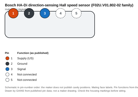
| Pin | Function (as published) | Typical ECU input | Wire note |
|---|---|---|---|
| 1 | Supply (US) | Sensor supply (5-18 V per maker) | — |
| 2 | Ground | Sensor ground | Return to sensor ground, not chassis |
| 3 | Signal | Crank/cam trigger input (digital, pull-up) | — |
| 4 | Not connected | Leave unconnected | — |
| 5 | Not connected | Leave unconnected | — |
Pin functions as published.2 The ECU-input and wire columns are our general guidance, not the maker's.
Connector: Autosport AS 5-way (ASL606-05PC-HE); mating part ASL006-05SC-HE (F02U.000.228-01)2 Connector library
Terminals and seals: Not listed: the data sheet gives the mating connector only.
How it's calibrated
ECU-neutral: enter these values in whichever ECU you use. Nominal values without the maker's tolerance band.
Trigger setup
- Trigger type: Hall effect (digital square wave).2
- Output: Open collector for 1 kΩ; pulse width 37-53 µs forward, 75-105 µs backward.2
- Max frequency: ≤ 10 kHz forward, ≤ 6 kHz backward.2
- Air gap: 0.4-1.0 mm (0.016-0.039 in).2
- Trigger edge: not published by the maker. Confirm the edge your ECU uses with a scope or a timing light before running the engine.
Native support across ECUs
| ECU platform | Status | How to set it up | Source |
|---|---|---|---|
| GAINS ECU2Concept | To be confirmed | INJ5-6 or IGN5-6 as a frequency input with the 2.2 kΩ pull-up, or CRANK/CAM (pins 13/15) for engine position; Hall pull-up on CRANK/CAM still open. | Medium3 |
| Haltech (Elite / Nexus) | Configurable (generic input) | One of the 6 synchronised pulsed inputs, which Haltech lists as usable for cam sensors or as frequency inputs; or the trigger/home inputs for engine position. | Medium5 |
| Link (G4X) | Configurable (generic input) | Trigger input; Link sells a Hall sensor kit listed for all Link ECUs. Wheel-speed input count not on the public page. | Medium6 |
| MoTeC (M1) | Unverified | The M150 page lists programmable digital inputs but does not name Hall speed sensors. | No public source |
| ECUMaster (EMU Black) | Configurable (generic input) | Vehicle speed input (Hall or VR), or one of 3 trigger inputs with Hall/VR selected in software. | Medium7 |
| AEM (Infinity) | Configurable (generic input) | Crank or cam Hall input (10 kΩ pull-up to 12 V per AEM's Series 5 spec). | Medium8 |
| MaxxECU | Configurable (generic input) | One of 4 extra digital/VR inputs listed for speed sensors, or a trigger input in digital mode. | Medium9 |
| Holley (Terminator X / EFI) | Unverified | Not checked: we cite only public product pages, and none for Holley covers this sensor. | No public source |
Third-party rows come only from each vendor's public product pages, sensor lists and spec sheets, retrieved on the dates listed in Sources; we do not use ECU software, help files, base maps or calibration files, and reproduce no vendor calibration values. "Preset listed" means the vendor publicly names this sensor; "Configurable" means a matching generic input is listed. Check the vendor's current documentation before buying.
Trademarks belong to their owners. Names are used only to identify compatible products; no endorsement is implied.
CAD and drawings
- Data sheetSpeed Sensor Hall-Effect HA-Di data sheet 69979403 (PDF)2Download from Bosch MotorsportNo login at last check; the maker may change this
We link to the maker's own downloads and do not rehost their CAD or data sheets: the maker's terms do not grant redistribution. Registration may be needed on the maker's site.
Wiring and installation
Supply to pin 1, ground to pin 2, signal on pin 3 to a digital input with a pull-up. To use direction, the input must time each pulse: Bosch's forward pulses are 37-53 µs wide and backward pulses 75-105 µs.2
Order the variant (0, 90, 180 or 270) that matches the angle between the sensor mounting and the target wheel; Bosch asks for that angle with the order.2
Failure modes and checks
Likely cause Air gap outside 0.4-1.0 mm
Check Measure the gap to the target wheel with feeler gauges and shim the sensor to Bosch's range.2
Likely cause No pull-up, or an ECU input expecting VR
Check The output is open collector rated for a 1 kΩ load: set the ECU input to Hall/digital with a pull-up to its supply.2
Likely cause Wrong variant for the mounting orientation, or the input cannot resolve pulse width
Check Check the variant against Bosch's drawing and confirm the input can time pulses of 40-100 µs.Medium2
Test it with a multimeter
- With the supply connected and a pull-up on the signal, the signal pin should switch between near 0 V and the pull-up voltage as a tooth passes (turn the engine slowly). Maker output: Open collector for 1 kΩ; pulse width 37-53 µs forward, 75-105 µs backward.2
Frequently asked
How does the Bosch HA-Di detect direction?
By pulse width. Each tooth gives a pulse about 45 µs wide when the wheel turns forward and about 90 µs when it turns backward, so an input that times the pulse can tell the two apart.2
What is the difference between HA-Di 0, 90, 180 and 270?
They are the same sensor for four mounting angles relative to the target wheel. Bosch asks you to specify the angle between the mounting and the wheel, and its drawings show each version against the direction of rotation.2
What is the pinout of the HA-Di?
Pin 1 supply, pin 2 ground, pin 3 signal; pins 4 and 5 are not connected. The connector is an AS 5-way, mating ASL006-05SC-HE.2
Related
Use it with GAINS
Bosch HA-Di direction-sensing Hall speed sensor (F02U.V01.802-02 family) on GAINS hardware
ECU2CRANK (VR or Hall, single-ended, adaptive threshold)
- Pins
- On the ECU2 pin map
- Pull-up
- To be confirmed
- Shielding
- Shielded, drain at the ECU end only
Shielded cable, shield to sensor ground at the ECU end only. Hall pull-up arrangement to be confirmed in the schematic.Medium3
GAINS hardware is pre-release concept design; pin numbers can change before release and none of it has been tested on a vehicle yet.34
Concept Pre-release hardware. Pin assignments come from the current design documents and may change.
Sources
9 sources
- Automotive Handbook, 10th edition (2018) · Robert Bosch GmbH / Wiley · book · retrieved 2026-11-04
- Speed Sensor Hall-Effect HA-Di data sheet 69979403 · Bosch Motorsport (Bosch Engineering GmbH) · vendor-doc · retrieved 2026-11-04
- internal GAINS internal: ECU2 concept and pin map v0.3 (hardware/mini-ecu/CONCEPT.md §3)
- internal GAINS internal: PDM2 input and output specification (hardware/mini-pdm/SPEC.md)
- Nexus R3 VCU (HT-193000) product page · Haltech · vendor-doc · retrieved 2026-11-04
- Hall effect sensor kit product page · Link Engine Management · vendor-doc · retrieved 2026-10-27
- EMU Black product page · ECUMaster · vendor-doc · retrieved 2026-11-04
- Infinity Series 5 hardware specification · AEM Electronics · vendor-doc · retrieved 2026-10-27
- MaxxECU RACE product page · MaxxECU · vendor-doc · retrieved 2026-11-04