

Bosch · Hall effect (digital)
Bosch HA-D 90 differential Hall speed sensor (F02U.V00.334-01)
The Bosch HA-D 90 (F02U.V00.334-01) is a differential Hall speed sensor that gives very repeatable falling-edge detection, up to 10 kHz, for crank or wheel speed. It is active high, open collector for a 1 kΩ load, runs on 5-18 V and needs a 0.4-1.0 mm air gap. Bosch notes it is not a true power-on sensor. Pins: 1 supply, 2 ground, 3 signal.2
Key specifications
Measures: Rotational speed from a ferromagnetic target wheel. Output: Hall effect (digital).
Not a true power-on sensor (needs target motion before the output is valid)
Sourced · medium2| Part number | Maker | Note |
|---|---|---|
| F02U.V00.334-01 | Bosch | HA-D 902 |
Pinout and connector
- Supply
- Ground / return
- Signal
- Shield
- Not used / not listed
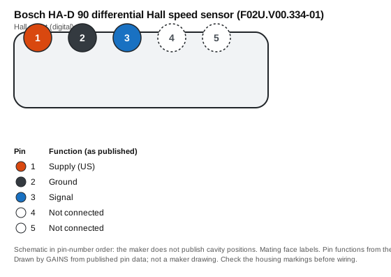
| Pin | Function (as published) | Typical ECU input | Wire note |
|---|---|---|---|
| 1 | Supply (US) | Sensor supply (5-18 V per maker) | — |
| 2 | Ground | Sensor ground | Return to sensor ground, not chassis |
| 3 | Signal | Crank/cam trigger input (digital, pull-up) | — |
| 4 | Not connected | Leave unconnected | — |
| 5 | Not connected | Leave unconnected | — |
Pin functions as published.2 The ECU-input and wire columns are our general guidance, not the maker's.
Connector: Autosport AS 5-way (ASL606-05PC-HE); mating part ASL006-05SC-HE (F02U.000.228-01)2 Connector library
Terminals and seals: Not listed: the data sheet gives the mating connector only.
How it's calibrated
ECU-neutral: enter these values in whichever ECU you use. Nominal values without the maker's tolerance band.
Trigger setup
Native support across ECUs
| ECU platform | Status | How to set it up | Source |
|---|---|---|---|
| GAINS ECU2Concept | To be confirmed | CRANK (pin 13) or CAM (pin 15) accept Hall in the concept; wheel speed goes on INJ5-6 or IGN5-6 as a frequency input. The Hall pull-up on CRANK/CAM is still open. | Medium3 |
| Haltech (Elite / Nexus) | Configurable (generic input) | One of the 6 synchronised pulsed inputs, which Haltech lists as usable for cam sensors or as frequency inputs; or the trigger/home inputs for engine position. | Medium5 |
| Link (G4X) | Configurable (generic input) | Trigger input; Link sells a Hall sensor kit listed for all Link ECUs. Wheel-speed input count not on the public page. | Medium6 |
| MoTeC (M1) | Unverified | The M150 page lists programmable digital inputs but does not name Hall speed sensors. | No public source |
| ECUMaster (EMU Black) | Configurable (generic input) | Vehicle speed input (Hall or VR), or one of 3 trigger inputs with Hall/VR selected in software. | Medium7 |
| AEM (Infinity) | Configurable (generic input) | Crank or cam Hall input (10 kΩ pull-up to 12 V per AEM's Series 5 spec). | Medium8 |
| MaxxECU | Configurable (generic input) | One of 4 extra digital/VR inputs listed for speed sensors, or a trigger input in digital mode. | Medium9 |
| Holley (Terminator X / EFI) | Unverified | Not checked: we cite only public product pages, and none for Holley covers this sensor. | No public source |
Third-party rows come only from each vendor's public product pages, sensor lists and spec sheets, retrieved on the dates listed in Sources; we do not use ECU software, help files, base maps or calibration files, and reproduce no vendor calibration values. "Preset listed" means the vendor publicly names this sensor; "Configurable" means a matching generic input is listed. Check the vendor's current documentation before buying.
Trademarks belong to their owners. Names are used only to identify compatible products; no endorsement is implied.
CAD and drawings
- Data sheetSpeed Sensor Hall-Effect HA-D 90 data sheet 69813003 (PDF)2Download from Bosch MotorsportNo login at last check; the maker may change this
We link to the maker's own downloads and do not rehost their CAD or data sheets: the maker's terms do not grant redistribution. Registration may be needed on the maker's site.
Wiring and installation
Supply to pin 1, ground to pin 2, signal on pin 3 to a Hall/digital input with a pull-up. Trigger on the falling edge, which is the edge Bosch specifies for repeatability.Medium2
Failure modes and checks
Likely cause Air gap outside 0.4-1.0 mm
Check Measure the gap to the target wheel with feeler gauges and shim the sensor to Bosch's range.2
Likely cause No pull-up, or an ECU input expecting VR
Check The output is open collector rated for a 1 kΩ load: set the ECU input to Hall/digital with a pull-up to its supply.2
Likely cause Differential sensor without true power-on: it cannot tell tooth from gap at standstill
Check Bosch qualifies camshaft use with a footnote; prefer a true power-on sensor for cam sync, or let the ECU sync after the engine turns.Medium21
Test it with a multimeter
- With the supply connected and a pull-up on the signal, the signal pin should switch between near 0 V and the pull-up voltage as a tooth passes (turn the engine slowly). Maker output: Open collector for 1 kΩ, active high.2
Frequently asked
Is the Bosch HA-D 90 a true power-on sensor?
No. Bosch states it is not a true power-on sensor, so its output is not valid until the target moves. That matters for cam sync at the first revolution, and Bosch marks camshaft use with a qualifying footnote.Medium21
What is the pinout of the HA-D 90?
Pin 1 supply, pin 2 ground, pin 3 signal; pins 4 and 5 are not connected, on an AS 5-way connector (mating ASL006-05SC-HE).2
What air gap does the HA-D 90 need?
0.4-1.0 mm (0.016-0.039 in) to a ferromagnetic target wheel. Outside that range pulses can drop out.2
Related
Use it with GAINS
Bosch HA-D 90 differential Hall speed sensor (F02U.V00.334-01) on GAINS hardware
ECU2CRANK (VR or Hall, single-ended, adaptive threshold)
- Pins
- On the ECU2 pin map
- Pull-up
- To be confirmed
- Shielding
- Shielded, drain at the ECU end only
Shielded cable, shield to sensor ground at the ECU end only. Hall pull-up arrangement to be confirmed in the schematic.Medium3
GAINS hardware is pre-release concept design; pin numbers can change before release and none of it has been tested on a vehicle yet.34
Concept Pre-release hardware. Pin assignments come from the current design documents and may change.
Sources
9 sources
- Automotive Handbook, 10th edition (2018) · Robert Bosch GmbH / Wiley · book · retrieved 2026-11-04
- Speed Sensor Hall-Effect HA-D 90 data sheet 69813003 · Bosch Motorsport (Bosch Engineering GmbH) · vendor-doc · retrieved 2026-11-04
- internal GAINS internal: ECU2 concept and pin map v0.3 (hardware/mini-ecu/CONCEPT.md §3)
- internal GAINS internal: PDM2 input and output specification (hardware/mini-pdm/SPEC.md)
- Nexus R3 VCU (HT-193000) product page · Haltech · vendor-doc · retrieved 2026-11-04
- Hall effect sensor kit product page · Link Engine Management · vendor-doc · retrieved 2026-10-27
- EMU Black product page · ECUMaster · vendor-doc · retrieved 2026-11-04
- Infinity Series 5 hardware specification · AEM Electronics · vendor-doc · retrieved 2026-10-27
- MaxxECU RACE product page · MaxxECU · vendor-doc · retrieved 2026-11-04